Samson 3349 Mounting And Operating Instructions
Aseptic angle valve with usp-vi diaphragm
Hide thumbs
Also See for 3349:
- Mounting and operating instructions (16 pages) ,
- Mounting and operating instructions (104 pages)
Table of Contents
Advertisement
Quick Links
EB 8048-21 EN
Translation of original instructions
Type 3349 Valve with Type 3277 Pneumatic
Actuator and Type 3730 Positioner
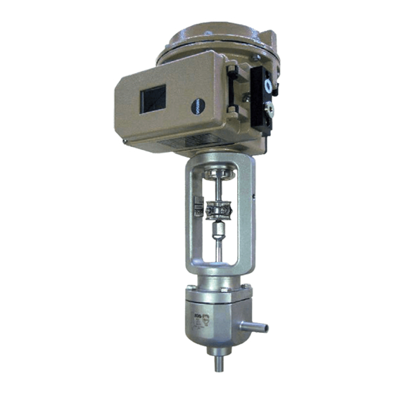
Type 3349 Aseptic Angle Valve with USP-VI diaphragm
In combination with an actuator, e.g. a SAMSON Type 3271 or
Type 3277 Pneumatic Actuator or Type 3379 Pneumatic Actuator
Edition March 2022
Note: This version of the
product is to be discontinued
shortly.
Replacement device:
Type 3349 HV01
These mounting and operating
instructions will then only apply
to valves already in use.
The mounting and operating
instructions u EB 8048-2
apply to the Type 3349 HV01.
They can be downloaded from
our website at
u www.samsongroup.com >
Service & Support >
Downloads > Documentation
Type 3349/3379 Control Valve with
Type 3724 Positioner
53-06
Advertisement
Table of Contents

Subscribe to Our Youtube Channel
Related Manuals for Samson 3349


Summary of Contents for Samson 3349
- Page 1 Type 3349 Valve with Type 3277 Pneumatic Type 3349/3379 Control Valve with Actuator and Type 3730 Positioner Type 3724 Positioner Type 3349 Aseptic Angle Valve with USP-VI diaphragm In combination with an actuator, e.g. a SAMSON Type 3271 or Type 3277 Pneumatic Actuator or Type 3379 Pneumatic Actuator Edition March 2022 53-06...
- Page 2 Note on these mounting and operating instructions These mounting and operating instructions assist you in mounting and operating the device safely. The instructions are binding for handling SAMSON devices. The images shown in these instructions are for illustration purposes only. The actual product may vary.
-
Page 3: Table Of Contents
Contents Safety instructions and measures ..............5 Notes on possible severe personal injury ............8 Notes on possible personal injury ..............8 Notes on possible property damage ..............10 Markings on the device ................12 Body inscription ...................12 Actuator nameplate ..................12 Material identification number ..............12 Design and principle of operation ..............14 Fail-safe positions ..................14 Versions ......................17... - Page 4 Decommissioning ..................51 Removal .....................53 11.1 Removing the valve from the pipeline .............53 11.2 Removing the actuator from the valve ............54 Repairs .......................54 12.1 Returning devices to SAMSON ..............54 Disposal ......................55 Annex......................56 14.1 After-sales service ..................56 14.2 Certificates ....................56 14.3 Spare parts ....................60...
-
Page 5: Safety Instructions And Measures
SAMSON. SAMSON does not assume any liability for damage resulting from the failure to use the de- vice for its intended purpose or for damage caused by external forces or any other external factors. - Page 6 Î Check with the plant operator for details on further protective equipment. Revisions and other modifications Revisions, conversions or other modifications of the product are not authorized by SAMSON. They are performed at the user's own risk and may lead to safety hazards, for example.
- Page 7 Start-up and shutdown procedures fall within the scope of the operator's duties and, as such, are not part of these mounting and operating instructions. SAMSON is unable to make any statements about these procedures since the operative details (e.g. differential pressures and temperatures) vary in each individual case and are only known to the operator.
-
Page 8: Notes On Possible Severe Personal Injury
Type 3724 Positioner − u AB 0100 for tools, tightening torques and lubricant − Manual u H 02: Appropriate Machinery Components for SAMSON Pneumatic Control Valves with a Declaration of Conformity of Final Machinery 1.1 Notes on possible severe personal injury DANGER Risk of bursting in pressure equipment. - Page 9 Risk of personal injury due to preloaded springs. Valves in combination with pneumatic actuators with preloaded springs are under ten- sion. These control valves with SAMSON pneumatic actuators can be identified by the long bolts protruding from the bottom of the actuator.
-
Page 10: Notes On Possible Property Damage
Safety instructions and measures WARNING Risk of personal injury due to residual process medium in the valve. While working on the valve, residual medium can flow out of the valve and, depending on its properties, cause personal injury, e.g. (chemical) burns. Î... - Page 11 Risk of valve damage due to the use of unsuitable tools. Certain tools are required to work on the valve. Î Only use tools approved by SAMSON (u AB 0100). Risk of valve damage due to the use of unsuitable lubricants. The lubricants to be used depend on the valve material. Unsuitable lubricants may cor- rode and damage surfaces.
-
Page 12: Markings On The Device
Markings on the device 2 Markings on the device 2.1 Body inscription The details on the valve version are lasered onto the front and back of the valve body (see Fig. 1). No nameplate is used. 2.2 Actuator nameplate Body See associated actuator documentation. inscription 2.3 Material identification number... - Page 13 11 CE marking or "Art. 4, Abs. 3" (PED · C 2014/68/EU) Characteristic: % = Equal percentage · L = Linear 12 If applicable, EAC mark including month and year of production 13 SAMSON material marking Fig. 2: Information on the valve body EB 8048-21 EN...
-
Page 14: Design And Principle Of Operation
The fail-safe position depends on the mount- ed actuator. Depending on how the com- The Type 3349 Angle Valve is preferably pression springs are arranged in the pneu- combined with a SAMSON Type 3271 or matic actuator, the valve has two different Type 3277 Pneumatic Actuator (see Fig. 3) - Page 15 5 Threaded bushing or stem 19 Washer seal A7 Actuator stem 20 Flange 6 Threaded pin A26 Stem connector clamps 23 V-ring packing 7 Travel indicator scale 24 USP-VI diaphragm Fig. 3: Type 3349 Valve for combination with a Type 3271 or Type 3277 Actuator EB 8048-21 EN...
- Page 16 2 Plug 34 Hex screw 3 Plug stem 36 Screw plug (test connection) or nipple (pipe) 15 Spring 40 Pipe 20 Valve bonnet 41 Bearing 23 V-ring packing Fig. 4: Type 3349 Valve for combination with a Type 3379 Actuator EB 8048-21 EN...
-
Page 17: Versions
Î Observe the maximum permissible actu- ator force. Micro-flow valve Note The Type 3349 Valve is also available as a micro-flow valve. If the travel range of the actuator is larger than the travel range of the valve, the spring Valve size... -
Page 18: Technical Data
(actuator Conformity and plug stem). Plant operators are responsi- The Type 3349 Valve bears both the CE and ble for deciding whether a guard is to be EAC marks of conformity. used. The decision is based on the risk posed by the plant and its operating conditions. - Page 19 Design and principle of operation Dimensions and weights Table 1: Dimensions of Type 3349 Angle Valve for mounting onto Type 3271 and Type 3277 Actuators ½ ¾ 1¼ 1½ 2½ mm 238 mm 70 1) mm 86 Weight kg 6 Length with welding ends (DIN version); dimensions of other connections and versions u T 8048-21...
- Page 20 1¼ 1½ Rated travel 1) Weight Length with welding ends (dimensions of other connections u T 8048-22) Weight with welding ends Table 3: Dimensions of Type 3349 as micro-flow valve for mounting onto Type 3379 Actua- – ¼ ½ ¾ Rated travel 1) DIN 11866, Series A Weight DIN 11866, Series B...
- Page 21 Design and principle of operation Dimensional drawings Type 3349 for mounting on Type 3379 Type 3349 for mounting on Type 3379 Actuator · Standard version Actuator · Micro-flow valve version EB 8048-21 EN...
-
Page 22: Shipment And On-Site Transport
2. Check the shipment for transportation Î Stay clear of suspended or moving damage. Report any damage to loads. SAMSON and the forwarding agent (re- Î Close off and secure the transport paths. fer to delivery note). 3. Determine the weight and dimensions of... -
Page 23: Transporting The Valve
Shipment and on-site transport 4.3.1 Transporting the valve WARNING Risk of personal injury due to the control The control valve can be transported using valve tipping over. lifting equipment (e.g. crane or forklift). Î Observe the valve's center of gravity. Î... -
Page 24: Lifting The Valve
Shipment and on-site transport 4.3.2 Lifting the valve the crane or forklift (see Fig. 6, Fig. 7 and Fig. 8). Make sure that the actuator To install a large valve into the pipeline, use stem and valve accessories are not dam- lifting equipment (e.g. crane or forklift) to lift aged. - Page 25 Shipment and on-site transport Lifting points on the control valve Fig. 6: Type 3349 with Type 3271 without Fig. 7: Type 3349 with Type 3271 with lifting lifting eyelet eyelet Fig. 8: Type 3349 with Type 3277 without Fig. 9: Type 3349/3379 lifting eyelet EB 8048-21 EN...
-
Page 26: Storing The Valve
Î Observe the storage instructions. vent cracking, do not bend them or hang Î Avoid long storage times. them up. Î Contact SAMSON in case of different − We recommend a storage temperature of storage conditions or longer storage 15 °C for elastomers. -
Page 27: Installation
5.1 Installation conditions depending on several variables and process conditions and are intended as recommen- Work position dations. Contact SAMSON if the lengths are significantly shorter than the recommended The work position for the control valve is the lengths. front view looking onto the operating con- trols (including valve accessories). -
Page 28: Preparation For Installation
For valves that are intended to be free of cavities, the control valve must be installed 5.2 Preparation for installation with the actuator on top: Î Contact SAMSON if the mounting posi- Before installation, make sure the following tion is not as specified above. conditions are met: Support and suspension −... -
Page 29: Mounting The Device
Risk of valve damage due to the use of Î Check any mounted pressure gauges to unsuitable tools. make sure they function properly. Î Only use tools approved by SAMSON Î When the valve and actuator are al- (u AB 0100). ready assembled, check the tightening torques of the bolted joints (u AB 0100). -
Page 30: Mounting The Actuator Onto The Valve
Mounting the actuator a) Version with Type 3271 or onto the valve Type 3277 Actuator Depending on the version, SAMSON control Refer to Fig. 11 valves are either delivered with the actuator Proceed as described in the actuator docu- already mounted on the valve or the valve mentation if the valve and actuator have not and actuator are delivered separately. - Page 31 To prevent the actuator stem from rotating, a locking pin with 3.5 mm diameter is re- quired. The locking pin (item no. 1281- 0066) can be ordered from SAMSON. 1. Undo the screws (34) on the valve bon- net (20). 2. Lift the valve bonnet (20) together with the plug (2), plug stem (3) and dia- phragm (24) off the body (1).
-
Page 32: Installing The Valve Into The Pipeline
Installation 5.4 Installing the valve into the 5. Completely retract the actuator stem to protect the plug from sparks during weld- pipeline ing. 6. Weld the valve free of stress into the NOTICE pipeline. Risk of valve damage due to work being 7. - Page 33 Installation WARNING WARNING WARNING Risk of hearing loss or deafness due to loud Risk of personal injury due to exhaust air noise. being vented. Noise emission (e.g. cavitation or flashing) While the valve is operating, air is vented may occur during operation caused by the from the actuator, for example, during process medium and the operating condi- closed-loop operation or when the valve...
-
Page 34: Leak Test
Installation To test the valve functioning before start-up Î Apply the maximum and minimum con- or putting back the valve into operation, per- trol signals to check the end positions of form the following tests: the valve while observing the movement of the actuator stem. -
Page 35: Start-Up
Start-up 6 Start-up Î Wear hearing protection when working near the valve. The work described in this section is only to be performed by personnel appropriately qualified to carry out such tasks. WARNING WARNING Crush hazard arising from actuator and WARNING plug stem moving in pneumatic control Risk of burn injuries due to hot or cold com-... -
Page 36: Operation
Operation 3. Check the valve to ensure it functions NOTICE properly. Diaphragm damage through the use of an incompressible medium. Closing the valve when the shut-off valves upstream and downstream of the valve are 7 Operation closed may lead to the diaphragm rupturing in plants with liquid media flowing through Immediately after completing start-up or put- them. - Page 37 Operation occur through the sudden venting of the Î Wear eye protection when working in pneumatic actuator or pneumatic valve ac- close proximity to the control valve. cessories not fitted with noise-reducing fit- tings. Both can damage hearing. WARNING Î Wear hearing protection when working near the valve.
-
Page 38: Troubleshooting
Malfunctions 7.1 CIP (cleaning-in-place) 8 Malfunctions CIP can be performed with commonly used Read hazard statements, warnings and cleaning fluids. caution notes in sections 1.1, 1.2 and 1.3. Î Observe the applicable hygiene regula- Depending on the operating conditions, tions. check the valve at certain intervals to prevent possible failure before it can occur. -
Page 39: Emergency Action
Malfunctions Malfunction Possible reasons Recommended action Actuator and plug stem Signal pressure too low Check the signal pressure. does not stroke through Check the signal pressure line for leakage. the entire range. Plug has become Fasten plug and plug stem together (see detached. -
Page 40: Servicing
Servicing 9 Servicing Î Allow components and pipelines to cool down or warm up to the ambient tem- The work described in this section is only to perature. be performed by personnel appropriately Î Wear protective clothing and safety qualified to carry out such tasks. gloves. - Page 41 Risk of valve damage due to the use of WARNING unsuitable tools. Risk of personal injury due to preloaded Î Only use tools approved by SAMSON springs. (u AB 0100). Actuators with preloaded springs are under tension. They can be identified by the long...
-
Page 42: Checking The Extent Of Servicing
1. Lay out the necessary material and tools to have them ready for the service work. Note 2. Put the control valve out of operation (see The control valve was checked by SAMSON section 10). before delivery. − Certain test results certified by SAMSON 3. -
Page 43: Replacing The Packing
Servicing Î After all service work is completed, check 13. Mount actuator. See associated actuator the control valve before putting it back documentation and section 5. into operation (see section 5.5). 14. Adjust lower or upper signal bench range. See associated actuator docu- 9.4.1 Replacing the packing mentation. - Page 44 Servicing 13. Screw the new plug (2) back onto the 21. Mount actuator. See associated actuator plug stem (3) again using a suitable tool. documentation and section 5. Align the plug stem with the mounted po- 22. Adjust lower or upper signal bench sition mark made earlier.
- Page 45 5 Threaded bushing 20 Flange A26 Stem connector clamps 6 Threaded pin 23 V-ring packing 7 Travel indicator scale 24 Diaphragm 10 Stem connector nut 34 Hex screw Fig. 12: Type 3349 Angle Valve for Type 3271 and Type 3277 Actuators EB 8048-21 EN...
-
Page 46: Service Work For Version With Type 3379 Actuator
3.5 mm diameter is re- tion 9.5.2). quired. The locking pin (item no. 1281- 10. Push the plug (2) together with plug stem 0066) can be ordered from SAMSON. (3) and diaphragm (24) into the valve bonnet (20). 9.5.1 Replacing the packing 11. -
Page 47: Replacing The Diaphragm And Plug
Servicing 18. Place the actuator and valve bonnet (20) tuator stem and pull it out of the valve together with the plug stem (3), plug (2) bonnet (20). and diaphragm (24) onto the body (1). 5. Unscrew the actuator (A) from the valve 19. - Page 48 Hex screw Plug Screw plug (test connection) or nipple (pipe) Plug stem Pipe Spring Bearing Valve bonnet Actuator V-ring packing Diaphragm Fig. 13: Type 3349 Angle Valve for Type 3379 Actuator · With additional packing (left) and with pipe (right) EB 8048-21 EN...
- Page 49 Servicing 19. Push the plug (2) together with plug stem 24. Screw the plug stem (3) together with (3) and diaphragm (24) into the valve plug (2) and diaphragm (24) onto the bonnet (20). actuator stem. Observe tightening torques. 20. Apply a suitable lubricant to the thread of the valve bonnet (20).
-
Page 50: Checking The Concentricity Of The Plug To The Plug Stem
3. If the concentricity deviates, use a suit- Contact your nearest SAMSON subsidiary able tool (e.g. plastic hammer) and hit or SAMSON's After-sales Service for infor- the plug until concentricity is achieved. mation on spare parts, lubricants and tools. Spare parts... -
Page 51: Decommissioning
Decommissioning 10 Decommissioning WARNING The work described in this section is only to Risk of personal injury due to pressurized be performed by personnel appropriately components and process medium being qualified to carry out such tasks. discharged. Î Do not loosen the screw of the test con- nection while the valve is pressurized. - Page 52 Decommissioning Î Before unblocking the actuator and plug in plants with liquid media flowing through stem after they have become blocked them. (e.g. due to seizing up after remaining in Î Only close the valve when the shut-off the same position for a long time), re- valves upstream and downstream of the lease any stored energy in the actuator valve are open.
-
Page 53: Removal
Removal 11 Removal (e.g. spring compression). See associat- ed actuator documentation. The work described in this section is only to be performed by personnel appropriately qualified to carry out such tasks. WARNING WARNING Risk of personal injury due to residual WARNING process medium in the valve. -
Page 54: Removing The Actuator From The Valve
RMA. Î Do not perform any repair work on your own. Note Î Contact SAMSON's After-sales Service Further information on returned devices and for service and repair work. how they are handled can be found at u www.samsongroup.com > Service &... -
Page 55: Disposal
Disposal 13 Disposal Î Observe local, national and internation- al refuse regulations. Î Do not dispose of components, lubricants and hazardous substances together with your household waste. EB 8048-21 EN... -
Page 56: Annex
You can reach our after-sales service at aftersalesservice@samsongroup.com. Addresses of SAMSON AG and its subsid- iaries The addresses of SAMSON AG, its subsid- iaries, representatives and service facilities worldwide can be found on our website (www.samsongroup.com) or in all SAMSON product catalogs. - Page 57 BNP Paribas N° compte 0002200215245 • Banque 3000401857 Tél.: +33 (0)4 72 04 75 00 • Fax: +33 (0)4 72 04 75 75 • E-mail: samson@samson.fr • Internet: www.samson.fr IBAN FR7630004018570002200215245 • BIC (code SWIFT) BNPAFRPPVBE Société par actions simpifiée au capital de 10 000 000 € • Siège social : Vaulx-en-Velin Crédit Lyonnais...
- Page 58 BNP Paribas N° compte 0002200215245 • Banque 3000401857 Tél.: +33 (0)4 72 04 75 00 • Fax: +33 (0)4 72 04 75 75 • E-mail: samson@samson.fr • Internet: www.samson.fr IBAN FR7630004018570002200215245 • BIC (code SWIFT) BNPAFRPPVBE Société par actions simpifiée au capital de 10 000 000 € • Siège social : Vaulx-en-Velin Crédit Lyonnais...
- Page 59 Annex Il, section 1. A. of the Directive 2006/42/EC For the following products: Pneumatic Control & Aseptic Angle Valve Type 3349-1/-7 consisting of the type 3349 Valve and Type 3271/Type 3277 Pneumatic Actuator or Type 3349 with Type 3379...
-
Page 60: Spare Parts
14.3 Spare parts Standard version for Type 3271 and Type 3277 Actuators Valve body Plug Plug stem Threaded bushing or stem seal Threaded pin Travel indicator scale 10 Stem connector nut 13 Lock nut 15 Spring 16 Hanger 19 Washer 20 Flange (assembly) 23 V-ring packing 24 USP-VI diaphragm 34 Hex screw... - Page 61 Standard version for Type 3379 Actuator Valve body Plug Plug stem Threaded pin 10 Stem connector nut 13 Lock nut 15 Spring 19 Washer 20 Valve bonnet 23 V-ring packing 24 USP-VI diaphragm 34 Hex screw 36 Screw plug (test connection) or nipple (pipe) 38 Gasket 40 Pipe (assembly)
- Page 62 Micro-flow valve version for Type 3271 and Type 3277 Actuators Valve body Plug Plug stem Threaded bushing or stem seal Threaded pin Travel indicator scale 15 Spring 16 Plate 19 Washer 20 Flange (assembly) 23 V-ring packing 24 USP-VI diaphragm 34 Hex screw 36 Screw plug (test connection) or nipple (pipe) 37 Countersunk screw...
- Page 63 Micro-flow valve version for Type 3379 Actuator Valve body Plug Plug stem Threaded pin 15 Spring 19 Washer 20 Valve bonnet 23 V-ring packing 24 USP-VI diaphragm 34 Hex screw 36 Screw plug (test connection) or nipple (pipe) 39 Washer 41 Bearing 42 Spacer 43 Snap ring EB 8048-21 EN...
- Page 64 EB 8048-21 EN SAMSON AKTIENGESELLSCHAFT Weismüllerstraße 3 · 60314 Frankfurt am Main, Germany Phone: +49 69 4009-0 · Fax: +49 69 4009-1507 samson@samsongroup.com · www.samsongroup.com...
Need help?
Do you have a question about the 3349 and is the answer not in the manual?
Questions and answers