Samson 3277 Mounting And Operating Instructions
Pneumatic actuator
Hide thumbs
Also See for 3277:
- Mounting and operating instructions (48 pages) ,
- Quick manual (2 pages) ,
- Mounting and operating instruction (112 pages)

Related Manuals for Samson 3277


Summary of Contents for Samson 3277
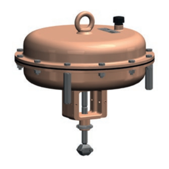
- Page 1 Pneumatic Actuator Type 3277 Fig. 1 · Type 3277 Pneumatic Actuator Fig. 2 · Type 3277-5 Pneumatic Actuator Mounting and Operating Instructions EB 8311 EN Edition July 2006...
- Page 2 In addition, the actuator can be equipped in a special version with a me- The Type 3277 Pneumatic Actuators with an chanically adjustable travel stop. effective diaphragm area of 240, 350 or 700 cm² are primarily mounted to control The signal pressure creates a force at the di- valves from the Series 240, 250 and 280.
- Page 3 350 cm² = 209 mm connection 700 cm² = 246 mm 12 Stem seal 12.1Dry bearing 13 Wiper 15 Ring nut 16 Stem connector Fig. 3 · Sectional diagram of Type 3277 with 240, 350 and 700 cm² effective diaphragm area EB 8311 EN...
- Page 4 (14.3) for the appropriate Type 3277 Actuator (Fig. 3) fail-safe action "Actuator stem extends" In the Type 3277 Actuator with fail-safe ac- or "Actuator stem retracts" with the mark tion "Actuator stem extends", the loading (14.4). See Fig. 4, bottom right.
- Page 5 Actuator stem Left attachment Right attachment Left attachment Right attachment extends retracts Dimension a = 188.5 with 15 mm travel and 185.5 with 20 mm travel Fig. 4 · Type 3277-5 Actuators with 120 cm effective diaphragm area EB 8311 EN...
-
Page 6: Operation
Reversing the fail-safe action "Actuator Note! stem extends" to "Actuator stem retracts" It is important for a trouble-free operation of the Type 3277 Actuator that the vent plug Note! (3) is not blocked. Actuators with 700 cm² (travel = 30 mm) - Page 7 Proceed in the same manner for the case with yoke. Type 3277-5 Actuator intended for the mi- 7. Insert springs (6) and place the top dia- cro-valve, but additionally attach the bush- ing (2.1) for the mechanical travel stop.
-
Page 8: Actuator With Handwheel
(27)" in place of "nut (1)". 2.1.2 Actuator with handwheel After reversing the operating direction: Type 3277 (Fig. 5) only 1. Replace the flange part (21) with ring 1. Undo lock nut (20) and relieve the nut (15) and coupling nut (25). - Page 9 Loading press. connection Ring nut Stem seal 12.1 Dry bearing Wiper Handwheel Lock nut Flange part Coupling Clamping sleeve Ring Coupling nut Threaded pin Spindle with nut 12.1 Fig. 5 · Type 3277 Actuator with additional handwheel EB 8311 EN...
-
Page 10: Adjusting The Travel Stop
Adjusting the travel stop Adjusting the travel stop (with Type 3277 in special version only) The travel stop can be adjusted upwards or downwards to 50% of the travel. Downward travel stop (actuator stem extends) 1. Undo the lock nut (34) and unscrew the cap (33). -
Page 11: Replacing The Diaphragm And Stem Seal
Dimensions and weights aphragm plate (7) (not necessary with Refer to the Data Sheet T 8310-1 EN dimen- Type 3277-5 as the diaphragm is held sions and weights of the different actuator versions. in place by the metal plate (7.1)). - Page 12 SAMSON AG · MESS- UND REGELTECHNIK Weismüllerstraße 3 · 60314 Frankfurt am Main · Germany Phone: +49 69 4009-0 · Fax: +49 69 4009-1507 EB 8311 EN Internet: http://www.samson.de...
Need help?
Do you have a question about the 3277 and is the answer not in the manual?
Questions and answers