
Subscribe to Our Youtube Channel
Related Manuals for SICK VICOTEC450


Summary of Contents for SICK VICOTEC450
- Page 1 O P E R A T I N G I N S T R U C T I O N S VICOTEC450 Visibility Measurement System Description Installation Operation...
- Page 2 Guarantee Information Specified product characteristics and technical data do not serve as guarantee declarations. © SICK AG. All rights reserved. VICOTEC450 · Operating Instructions · 8011767 V 2.3 · © SICK AG...
- Page 3 Hazard or unsafe practice which could result in personal injury or property damage. NOTICE Hazard which could result in property damage. Information Symbols Important technical information for this product Supplementary information Link to information at another place VICOTEC450 · Operating Instructions · 8011767 V 2.3 · © SICK AG...
-
Page 4: Table Of Contents
Safety information and protective measures ....... . . 9 Using the VICOTEC450 for safety-critical measuring tasks ..... . - Page 5 Putting out of operation ............95 VICOTEC450 · Operating Instructions · 8011767 V 2.3 · © SICK AG...
- Page 6 Spare parts ..............116 VICOTEC450 · Operating Instructions · 8011767 V 2.3 · © SICK AG...
-
Page 7: Important Information
Important information VICOTEC450 Important information Main hazards Intended use Responsibility of user Using the VICOTEC450 for safety-critical measuring tasks (fire detection and signalisation) VICOTEC450 · Operating Instructions · 8011767 V 2.3 · © SICK AG... -
Page 8: Main Hazards
Main hazards 1. 1 Hazards through electrical equipment 1.1.1 The VICOTEC450 measuring system is operational equipment for use in industrial high voltage plants. WARNING: Danger through mains voltage Disconnect mains lines before working on mains connections or parts carrying mains voltage. -
Page 9: Responsibility Of User
1.3.1 Designated users The VICOTEC450 measuring system may only be operated by skilled technicians who, based on their technical training and knowledge as well as knowledge of the relevant regulations, can assess the tasks given and recognize the hazards involved. -
Page 10: Using The Vicotec450 For Safety-Critical Measuring Tasks
● Plants with safety risks must always be redundantly monitored by suitable metrological equipment. Therefore the VICOTEC450 may not be used as the only link in a safety chain. ● The operator is always responsible for any switching thresholds or definition of switch- ing criteria. -
Page 11: Product Description
Product Description VICOTEC450 Product Description VICOTEC450 mode of operation Device components VICOTEC450 · Operating Instructions · 8011767 V 2.3 · © SICK AG... -
Page 12: Vicotec450 Mode Of Operation
Purge air Blower Processor board Exhaust air hose Analog output 0 ... 20 mA Relay outputs 90 ... 250 V AC Analog inputs Digital inputs Interface for control system VICOTEC450 · Operating Instructions · 8011767 V 2.3 · © SICK AG... - Page 13 Basic layout of a measuring unit without fog elimination Tunnel traffic area VCME measuring unit MCU control unit Air inlet Air intake hose Measuring cell Heating chamber Air filter Blower Exhaust air hose VICOTEC450 · Operating Instructions · 8011767 V 2.3 · © SICK AG...
-
Page 14: Scattered Light Measurement Principle
The scattered light intensity is converted in the device to the k value used for visibility measurement which is then output as the measured value. The basis is a factory calibration of the VICOTEC450 with the transmission meter normally used. VICOTEC450 · Operating Instructions · 8011767 V 2.3 · © SICK AG... -
Page 15: Response Time
● If the start timepoint or cycle interval are changed, a check cycle timed between parameter setting and new start timepoint is still carried out. ● Changes to the interval time are first effective after the next start timepoint. VICOTEC450 · Operating Instructions · 8011767 V 2.3 · © SICK AG... - Page 16 Figure 5 Contamination measurement Laser module Aperture 1 Aperture 2 Receiver in measuring position Light trap Measuring cell Reference position at cycle start Reference position at cycle end Guideway VICOTEC450 · Operating Instructions · 8011767 V 2.3 · © SICK AG...
-
Page 17: Device Components
Exhaust air hose Air intake hose Connection cable Power cable Air inlet with protective grating and coarse filter Cover for connections option Cover for connections with integrated air inlet VICOTEC450 · Operating Instructions · 8011767 V 2.3 · © SICK AG... -
Page 18: Communication Between Measuring Unit And Control Unit
24 V DC from the power supply unit in the control unit via the connection cable. For larger distances (→ p. 31, §3.1.5) or bus connection, integrate an optional power supply unit in the measuring unit. VICOTEC450 · Operating Instructions · 8011767 V 2.3 · © SICK AG... - Page 19 This increases the functional reliability of the measuring system and reduces maintenance frequency. VICOTEC450 · Operating Instructions · 8011767 V 2.3 · © SICK AG...
- Page 20 MCU is too large (voltage loss too high in the line) or when sev- eral measuring units are connected to one MCU (bus variant) VICOTEC450 · Operating Instructions · 8011767 V 2.3 · © SICK AG...
- Page 21 - N: Without Misc. - N: Without special features Example: VCME-24-P-2-F-N 24 V DC from MCU With flow measurement With 2x optional temperature measurement With fog elimination Without special features VICOTEC450 · Operating Instructions · 8011767 V 2.3 · © SICK AG...
-
Page 22: Mcu Control Unit
1 relay 2 relay 3 relay 4 relay 5 BUS - S/E unit 1 Term VICOTEC450 · Operating Instructions · 8011767 V 2.3 · © SICK AG... - Page 23 – Temperature external 2x – Dust concentration – k value – Visibility 2 measured values (see graphic display) Text display and 8 diagnosis values (→ p. 85, Fig. 80) VICOTEC450 · Operating Instructions · 8011767 V 2.3 · © SICK AG...
- Page 24 (MCU in 19” rack). The module is connected to the con- nection board by an associated cable. Profibus DP-V0 to transfer via RS485 in accordance with DIN 19245 Part 3 as well as IEC 61158. VICOTEC450 · Operating Instructions · 8011767 V 2.3 · © SICK AG...
- Page 25 - N: No special features EX certification - N: Without EX certification Software - E: Emission measurement : Maximum number of all modules of the same type = 4 VICOTEC450 · Operating Instructions · 8011767 V 2.3 · © SICK AG...
-
Page 26: Fastening Set
Stainless steel only Measuring unit, control unit and (2031891) 2x hexagon screw 8*55 A4 connection box option in stain- less steel housing 4M8-1.4529 4x Fischer tie bolt FAZ 8/10 C Aggressive ambi- (2031887) ent air VICOTEC450 · Operating Instructions · 8011767 V 2.3 · © SICK AG... -
Page 27: Assembly And Installation
Assembly and Installation VICOTEC450 Assembly and Installation Project planning Assembly Installation VICOTEC450 · Operating Instructions · 8011767 V 2.3 · © SICK AG... -
Page 28: Project Planning
(EU Directive 2004/54/EC Minimum safety requirements in tunnels) because two-way traffic cannot generally be excluded. If the VICOTEC450 is to be used for smoke detection as well, the distance between two neighboring measuring points which serve as optical smoke detector shall not be larger than 100 m to 150 m. - Page 29 Blower ● Dust particles can deposit in the air intake hoses → reduced cross- Measuring air feed for further evaluation systems (e.g. SIDOR) section Pipe manifold Air filter VICOTEC450 · Operating Instructions · 8011767 V 2.3 · © SICK AG...
-
Page 30: Installation Locations
● The exhaust air hose must not be much longer than the air intake hose. ● The air pressure at the air intake location and at the location where the VICOTEC450 exhaust air flows back into the environment must be approximately the same. -
Page 31: Connection Cable
Connection of air intake and exhaust air hoses when downward slope not available Measuring unit Exhaust air hose Air intake hose SICK can deliver a set comprising the air intake and exhaust air hoses with lengths of 5 m, 10 m and 15 m. Connection cable 3.1.5... -
Page 32: Assembly
Drill the holes as shown in p. 33, Fig. 16 (distances in accordance with Fig. 15). Insert dowels (fastening set 4D8-1.4571/PA, 2M8-1.4571) or tie bolts (fastening set 4M8-1.4529). Fasten the measuring unit with the hexagon head screws or nuts. VICOTEC450 · Operating Instructions · 8011767 V 2.3 · © SICK AG... - Page 33 Installing the installation plate option ∅ 10 192.5 > 550 Clearance for cables Clearance for opening the door, minimum sideways distance to passing vehicles when mounted on the tunnel wall VICOTEC450 · Operating Instructions · 8011767 V 2.3 · © SICK AG...
-
Page 34: Installing The Air Inlet With Protective Grating
Installing the air inlet with protective grating 3.2.2 Figure 19 Installation dimensions for wall mounting ∅ 5,5 Clearance for the air intake hose > 200 Minimum distance to passing vehicles VICOTEC450 · Operating Instructions · 8011767 V 2.3 · © SICK AG... -
Page 35: Installing The Control Unit With Wall Housing
● The MCU control unit can be installed up to 1200 m away from the measuring unit when a suitable cable is used. ● We recommend installing the MCU in an operational room for trouble-free communication with the VICOTEC450. VICOTEC450 · Operating Instructions · 8011767 V 2.3 · © SICK AG... -
Page 36: Installing The Connection Box Option
Install the temperature sensors of the option temperature measurement with 2x temperature sensor in the traffic area of the tunnel so that optimal temperature monitoring for early fire detection is possible. VICOTEC450 · Operating Instructions · 8011767 V 2.3 · © SICK AG... -
Page 37: Installation
● We cannot grant any warranty for proper system function when cables which do not comply with the above specifications are used. ● Always use cables of the same type and ensure continuous shielding. VICOTEC450 · Operating Instructions · 8011767 V 2.3 · © SICK AG... -
Page 38: Connecting The Control Unit With Wall Housing
Connect mains cable to terminals L1, N, PE of the MCU (→ Fig. 24). Close off unused cable openings with dummy plugs. VICOTEC450 · Operating Instructions · 8011767 V 2.3 · © SICK AG... - Page 39 RS485 A -24 V Closed Closed Note Onsite cable in accordance with p. 37, §3.3.1 To open, connect the plug-in connector to the plug on the measuring unit. VICOTEC450 · Operating Instructions · 8011767 V 2.3 · © SICK AG...
- Page 40 37, §3.3.1 Switching position of the relay contacts in currentless condition Measuring unit Plug assignment (View on pin side) RS485 B RS485 A Plug Socket -24 V +24 V VICOTEC450 · Operating Instructions · 8011767 V 2.3 · © SICK AG...
- Page 41 (→ p. 37, §3.3.1) VCME 1 VCME 8 VCME 2 to 7 Plug assignment (View on pin side) RS485 B RS485 A Plug Plug Socket Socket -24 V +24 V VICOTEC450 · Operating Instructions · 8011767 V 2.3 · © SICK AG...
- Page 42 ● Terminal assignment, DO module signal relay (4 NO contacts) Figure 32 Terminal assignment, digital output module signal relay (4 NO contacts) Digital output module module carrier n.o. com. com. n.o. n.o. com. com. n.o. VICOTEC450 · Operating Instructions · 8011767 V 2.3 · © SICK AG...
-
Page 43: Connecting The Control Unit In 19" Rack
Output relay 5 (limit value) n.c. n.o. Digital input d in 1 d in 2 d in 3 d in 4 Analog output Analog input AI 1 AI 2 VICOTEC450 · Operating Instructions · 8011767 V 2.3 · © SICK AG... - Page 44 I/O-MODULE SICK ULTI ONTROL POWER FAILURE POWER TxD RxD MAINTENANCE ERROR REQUEST 6 5 4 3 2 Plug-in slot Connection is made on terminals 101-180 of the backplane. VICOTEC450 · Operating Instructions · 8011767 V 2.3 · © SICK AG...
- Page 45 106 b 106 b 107 c 107 c 107 c 108 d 108 d 108 d 109 -gnd 109 -gnd 109 -gnd 110 scr 110 scr 110 scr VICOTEC450 · Operating Instructions · 8011767 V 2.3 · © SICK AG...
-
Page 46: Connecting The Measuring Unit(S)
Closed Plug-in connector (scope of delivery) Onsite cable 3 x 1.5 mm² (e.g. NYMHY3x 1.5 mm²) Measuring unit Plug-in connector (scope of delivery) Onsite cable Onsite mains connection VICOTEC450 · Operating Instructions · 8011767 V 2.3 · © SICK AG... - Page 47 (adhere to the equipment-specific assignment when several measuring units with this option are used!) VICOTEC450 · Operating Instructions · 8011767 V 2.3 · © SICK AG...
-
Page 48: Terminating The Vcme - Mcu Connection
Processor board Jumper VCME 1 VCME 2 VCME 8 MCU in bus middle AB x = connection box option x VCME 1 VCME 2 VCME 8 Processor board Jumper VICOTEC450 · Operating Instructions · 8011767 V 2.3 · © SICK AG... -
Page 49: Bus Addressing
The address assigned to a measuring unit is shown on a label on the unit door. Figure 40 Measuring unit addressing per hardware Processor board Jumper not set Jumper set Address Jumper Address Jumper Address Jumper Address Jumper VICOTEC450 · Operating Instructions · 8011767 V 2.3 · © SICK AG... - Page 50 Assembly and Installation Software addressing Alternatively, addressing can also be assigned in SOPAS ET (→ Fig. 41). To do so, connect the measuring system to SOPAS ET, select the ”VICOTEC450” device file and set the measuring system to ”Maintenance” mode. NOTICE: No jumpers may be set (→...
-
Page 51: Startup And Configuring
Startup and Configuring VICOTEC450 Startup and Configuring Basics Customizing the configuration Configuring optional modules Operating/configuring via the LC-Display option VICOTEC450 · Operating Instructions · 8011767 V 2.3 · © SICK AG... -
Page 52: Basics
Prerequisite is that assembly and installation have been completed as described in Section 3. The VICOTEC450 is delivered with default values set at the factory so that start-up primarily involves checking cable and hose connections (visual control) and switching on the mains voltage. - Page 53 Startup and Configuring Figure 42 Installing the USB driver VICOTEC450 · Operating Instructions · 8011767 V 2.3 · © SICK AG...
-
Page 54: Connecting The Device
If required, select the desired language in the "Tools / Language" menu (→ p. 55, Fig. 45→ p. 55, Fig. 45), confirm with "OK", and restart the program. VICOTEC450 · Operating Instructions · 8011767 V 2.3 · © SICK AG... -
Page 55: Configuring The Interface
MCU and Laptop/PC, click the "Advanced..." button and configure in accordance with Fig. 46 (settings only required during the first connection to the measuring system). Figure 46 COM port selection and configuration VICOTEC450 · Operating Instructions · 8011767 V 2.3 · © SICK AG... - Page 56 Click "Add ", enter the IP address and confirm with "OK". Figure 47 Ethernet interface selection (example settings) Click "Advanced..." and configure the interface in accordance with Fig. 48. Figure 48 Configuring the Ethernet interface VICOTEC450 · Operating Instructions · 8011767 V 2.3 · © SICK AG...
-
Page 57: Connecting Using The "Network Scan Assistant" Directory
The following message appears when no device is found (troubleshooting, see Service Manual): Problems with Ethernet connections can be caused by incorrect addressing → contact system administrator. Confirm search for connected devices with "OK". VICOTEC450 · Operating Instructions · 8011767 V 2.3 · © SICK AG... -
Page 58: Connecting Using The "Connection Wizard" Menu
"Internet Protocol (IP)" for connection via Ethernet). Figure 51 Selecting the interface Check the interface configuration for settings in accordance with p.57, §4.1.3.2 and change accordingly if necessary. Click "Next >". VICOTEC450 · Operating Instructions · 8011767 V 2.3 · © SICK AG... - Page 59 Startup and Configuring Figure 52 Searching for connected devices Connection via COM port Connection via Ethernet The following message appears when no device is found (troubleshooting, see Service Manual): VICOTEC450 · Operating Instructions · 8011767 V 2.3 · © SICK AG...
-
Page 60: Selecting The Device
Activate the checkbox of the required device file in the "Connection Wizard / Found devices" (→ p. 59, Fig. 52) and click "Next >". This transfers the device file to the "Project Tree" window. Figure 54 Transferring the device file VICOTEC450 · Operating Instructions · 8011767 V 2.3 · © SICK AG... -
Page 61: Information On Using The Program
Display, inquiries as well as all parameters required for service tasks (e.g. diagnosis and clearance of possible malfunctions) *): Depends on the program version The level 1 password is contained in the Annex. Figure 55 Entering the password VICOTEC450 · Operating Instructions · 8011767 V 2.3 · © SICK AG... -
Page 62: Online Help
4.1.5 Individual menus and setting options are described in detail in the Online Help and are therefore not described further here. Figure 56 Online Help Installed program version VICOTEC450 · Operating Instructions · 8011767 V 2.3 · © SICK AG... -
Page 63: Customizing The Configuration
(→ p. 61, §4.1.4), and set the measuring system to "Maintenance" mode (open the "Maintenance/Maintenance" directory, activate the "Maintenance on/off" checkbox, and press "Set State". Use device file "MCU" to configure. Figure 57 Setting "Maintenance" mode VICOTEC450 · Operating Instructions · 8011767 V 2.3 · © SICK AG... -
Page 64: Assigning The Sensors
All measuring units connected to the MCU must be activated for correct communication by checking them in the "Connected sensors" group in the "Configuration / System Configuration" directory (→ p. 65, Fig. 59) (correct when necessary). VICOTEC450 · Operating Instructions · 8011767 V 2.3 · © SICK AG... -
Page 65: Assigning The Measuring System To The Installation Location
Measuring unit and MCU can be assigned explicitly to the respective measuring location. Select "Configuration / Application Selection“ directory (→ p. 64, Fig. 58) for the MCU. Move the "Vicotec450" device file into the "Project tree" window and select the "Over- view" directory for the measuring unit. -
Page 66: Defining The Check Cycle
Function check inter- Time between two check cycles (recommended value 24 h) Function Check Start Hours Defines a start timepoint in hours, minutes and seconds Time Minutes Seconds VICOTEC450 · Operating Instructions · 8011767 V 2.3 · © SICK AG... -
Page 67: Configuring The Analog Output
(measuring signal of a measuring unit) to the standard analog output (AO), and to define the values for Live Zero and measuring range. VICOTEC450 · Operating Instructions · 8011767 V 2.3 · © SICK AG... - Page 68 (*) has not been ordered. Assignment is made by SICK Service when options are added later. : Only important for special applications VICOTEC450 · Operating Instructions · 8011767 V 2.3 · © SICK AG...
-
Page 69: Configuring The Analog Inputs
No error is reported for underflow or overflow of the set current range (LZ to 20 mA). Active An error is reported for underflow or overflow of the set current range (LZ to 20 mA). VICOTEC450 · Operating Instructions · 8011767 V 2.3 · © SICK AG... -
Page 70: Configuring The Limit Value Relay
(*) has not been ordered. Assignment is made by SICK Service when options are added later. : Only important for special applications VICOTEC450 · Operating Instructions · 8011767 V 2.3 · © SICK AG... -
Page 71: Calibrating For Dust Concentration Measurement
In this case, the regression coefficients set in the measuring unit and the measuring range set in the MCU may not be changed anymore. The dust concentration is displayed in mg/m³ on the LC-Display as an uncali- brated value. VICOTEC450 · Operating Instructions · 8011767 V 2.3 · © SICK AG... - Page 72 "Parameter / Capt_CoeffReg_Conc" directory Switch the measuring unit back to "Measure" mode after entering the coefficients. This method allows changing the parameters for the selected measuring range as desired. VICOTEC450 · Operating Instructions · 8011767 V 2.3 · © SICK AG...
-
Page 73: Setting The Response Time
The flow rate is adjusted at the factory so that no further work is required onsite. Changes may be made only by trained personnel (user level "Service" is required, see Service Manual). VICOTEC450 · Operating Instructions · 8011767 V 2.3 · © SICK AG... -
Page 74: Data Backup
The name of the file to be stored can be chosen freely. It is useful to specify a name with a reference to the sampling point involved (name of the company, equipment name). Figure 68 "Project / Save Project" menu VICOTEC450 · Operating Instructions · 8011767 V 2.3 · © SICK AG... -
Page 75: Starting Normal Measuring Operation
To do this, switch to the "Maintenance / Maintenance" directory, deactivate the "Maintenance on/off" checkbox and click "Set State" (→ Fig. 69). Standard start-up is now completed. Figure 69 Setting the operational state VICOTEC450 · Operating Instructions · 8011767 V 2.3 · © SICK AG... -
Page 76: Configuring Optional Modules
Configure in accordance with → p. 67, §4.2.5 (→ p. 68, Fig. 63). The basic settings ("Analog Outputs - General Overview" subdirectory; → p. 67, Fig. 62) apply to all available analog outputs in the same manner. VICOTEC450 · Operating Instructions · 8011767 V 2.3 · © SICK AG... -
Page 77: Optional Digital Outputs
Source sensor Selection of the component: - Sensor 1 to 8 when the device status is to be output - MCU when limit values are to be reported VICOTEC450 · Operating Instructions · 8011767 V 2.3 · © SICK AG... - Page 78 To check whether relays switch as intended, measured values which exceed the configured limits must be created. In addition, a continuity tester can be connected to the respective relay output for an external check. VICOTEC450 · Operating Instructions · 8011767 V 2.3 · © SICK AG...
-
Page 79: Assigning And Configuring Limit Value Switches To Optional Digital Outputs
Assigning and configuring limit value switches to optional digital outputs 4.3.1.3 Select the ”Configuration / Limit Values Switches” directory” for assigning. Configure in accordance with → p. 70, §4.2.7. Figure 73 ”Configuration / Limit Values Switches” directory VICOTEC450 · Operating Instructions · 8011767 V 2.3 · © SICK AG... -
Page 80: Configuring Optional Interface Modules
Configure the Interface module as required. Figure 74 "Configuration / System Configuration" directory GSD file and measured value assignment are available for the Profibus DP module on request. VICOTEC450 · Operating Instructions · 8011767 V 2.3 · © SICK AG... -
Page 81: Configuring The Ethernet Module
Enter the desired network configuration in the "Ethernet Interface Configuration“ group and click "Reset module" under "Expansion module information". Figure 75 "Configuration / IO Configuration / Interface Module" directory new address VICOTEC450 · Operating Instructions · 8011767 V 2.3 · © SICK AG... - Page 82 Click "Advanced..." in the "Internet Protocol (IP)“ directory. Select port address "2111" and confirm with "OK" (all other settings are factory settings in accordance with Fig. 77). VICOTEC450 · Operating Instructions · 8011767 V 2.3 · © SICK AG...
- Page 83 VICOTEC450 manufacturer is not responsible. Increasing the value in field "Scan timeout" from 500 ms to 3000 ms can minimize communication problems. VICOTEC450 · Operating Instructions · 8011767 V 2.3 · © SICK AG...
-
Page 84: Operating/Configuring Via The Lc-Display Option
When connecting several measuring units to one MCU, the measured values of the individual measuring units are shown in succession. ● Display the contrast setting (press the button at least 2.5 s) VICOTEC450 · Operating Instructions · 8011767 V 2.3 · © SICK AG... -
Page 85: Menu Structure
" (moves the cursor to the right) buttons. → Select the desired value using the "^" and/or "→" buttons and write it to the device with "Save" (confirm 2x). VICOTEC450 · Operating Instructions · 8011767 V 2.3 · © SICK AG... - Page 86 Menu structure for configuring a Setting the MCU variant The following steps are required to set the MCU for the VICOTEC450 measuring unit to be connected (→ p. 64, §4.2.1), : Set the MCU to "Maintenance" mode, select the "MCU Variant" submenu, and select the type "Universal (Bus)".
-
Page 87: Measuring Unit (When Setting To Measure The Dust Concentration)
2 cc1 XXXX 3 cc0 sensor/1 /param Back Save Back Save Back Save Back Enter Parameter Parameter Parameter Password 000.000 -06.780 XXXX Back Save Back Save Back Save VICOTEC450 · Operating Instructions · 8011767 V 2.3 · © SICK AG... -
Page 88: Using Sopas Et To Modify Display Settings
Range low Values for separate scaling of the measured value bar independent of the analog out- Range high VICOTEC450 · Operating Instructions · 8011767 V 2.3 · © SICK AG... - Page 89 Visibility [m] : The next sequential measured variable moves up one position when an option has not been ordered. Assignment is made by SICK Service when options are added later. : Only important for special applications VICOTEC450 · Operating Instructions · 8011767 V 2.3 · © SICK AG...
- Page 90 Startup and Configuring VICOTEC450 · Operating Instructions · 8011767 V 2.3 · © SICK AG...
-
Page 91: Maintenance
Maintenance VICOTEC450 Maintenance General information Maintaining the measuring unit Putting out of operation VICOTEC450 · Operating Instructions · 8011767 V 2.3 · © SICK AG... -
Page 92: General Information
● Examining installed air intake and exhaust air hoses ● Checking the door of the measuring unit ● Exchanging the air filter of the measuring unit. Switch the VICOTEC450 to "Maintenance" mode before starting any maintenance work (→ p. 63, §4.2). WARNING: All activities must be carried out in line with the relevant safety regulations and instructions (→... -
Page 93: Maintaining The Measuring Unit
Clean the optics carefully with cleaning sticks and, if necessary, the light trap as well. Close the door again tightly (tighten the lock screws firmly). Figure 84 Cleaning the optics Sender lens Receiver optics Aperture Light trap VICOTEC450 · Operating Instructions · 8011767 V 2.3 · © SICK AG... -
Page 94: Cleaning The Coarse Filter In The Air Inlet
Close the door again tightly (tighten the lock screws firmly). Reconnect the mains voltage. Figure 85 Replacing the air filter Knurled nut Housing cover Air filter VICOTEC450 · Operating Instructions · 8011767 V 2.3 · © SICK AG... -
Page 95: Putting Out Of Operation
Maintenance Putting out of operation 5 . 3 Put the VICOTEC450 out of operation during longer tunnel closures or construction work causing dust in the tunnel. Alternatively, the VICOTEC450 can still be operated in such cases when air intake and exhaust air lines are connected to each other so that neither dust nor humidity can penetrate. - Page 96 Maintenance VICOTEC450 · Operating Instructions · 8011767 V 2.3 · © SICK AG...
-
Page 97: Malfunctions
Malfunctions VICOTEC450 Malfunctions General information Measuring unit Control unit VICOTEC450 · Operating Instructions · 8011767 V 2.3 · © SICK AG... -
Page 98: General Information
Detailed information on current device status is provided by the „Monitor/System state - details" (measuring unit) or "Diagnosis/Errors/Warnings" (MCU) directories.. Connect the measuring system to SOPAS ET and start the device file "Vicotec450" or "MCU" (→ p. 54, §4.1.3 and → p. 61, §4.1.4) to display the relevant information. -
Page 99: Measuring Unit
Current warning or error messages, or earlier messages stored in the error memory, can be shown by selecting "actual" or "memory" in the "Selection" window ("Device malfunction" group).→ p. 99, Fig. 87 VICOTEC450 · Operating Instructions · 8011767 V 2.3 · © SICK AG... -
Page 100: Replacing The Fuse For The Optional Power Supply Unit
Unscrew the fuse holder, replace the defective fuse and screw the fuse holder in again. Close the door tightly. Figure 88 Fuse holder for optional power supply unit Fuse holder VICOTEC450 · Operating Instructions · 8011767 V 2.3 · © SICK AG... -
Page 101: Control Unit
The number of optional modules ● No parameters set for DO does not match the number of ● Connection error §4.3.1). digital outputs configured. ● Module failure Contact SICK Service. VICOTEC450 · Operating Instructions · 8011767 V 2.3 · © SICK AG... - Page 102 Correct application settings (→ error sensor changed p. 64, §4.2.1). Testmode enabled MCU in "Test" mode. Deactivate "System Test" mode ("Maintenance" directory) Figure 90 "Overview" directory VICOTEC450 · Operating Instructions · 8011767 V 2.3 · © SICK AG...
-
Page 103: Replacing The Fuse
Replace the defective fuse (→ p. 116, §7.6). Close and attach the fuse holder. Close the door and connect mains voltage. Figure 91 Replacing the fuse Fuse holder Microfuse VICOTEC450 · Operating Instructions · 8011767 V 2.3 · © SICK AG... - Page 104 Close fuse holder. Insert control unit and reconnect the mains voltage. Figure 92 Replacing the fuse Power supply unit with plug-in connection Power supply unit with terminal connection VICOTEC450 · Operating Instructions · 8011767 V 2.3 · © SICK AG...
-
Page 105: Specifications
Specifications VICOTEC450 Specifications Technical Data Dimensions, Part Nos. Installation accessories Options Consumable parts for 2-year operation Spare parts Password VICOTEC450 · Operating Instructions · 8011767 V 2.3 · © SICK AG... -
Page 106: Technical Data
Laser class 2; power < 1 mW;wavelength approx. 650 nm; service life approx. 100,000 h (MTBF) at 20 °C Electrical safety In accordance with EN 61010-1 Blower output Approx. 30 ... 35 l/min VICOTEC450 · Operating Instructions · 8011767 V 2.3 · © SICK AG... -
Page 107: Dimensions, Part Nos
Ø 16Ø 9 Name Part No. VCME-24-N-0-N measuring unit 1040575 Type code → p. 18, §2.2.3 VCME-24-N-0-F measuring unit 1040691 VCME-WR-N-0-N measuring unit 1040692 VCME-WR-N-0-F measuring unit 1040693 VICOTEC450 · Operating Instructions · 8011767 V 2.3 · © SICK AG... -
Page 108: Air Inlet With Protective Grating
Name Part No. Air inlet with protective grating for wall fitting 2040848 Air inlet with protective grating for intermediate ceiling fitting 2040875 VICOTEC450 · Operating Instructions · 8011767 V 2.3 · © SICK AG... -
Page 109: Cover With Integrated Air Inlet
Part No. Cover with integrated air inlet 2040850 Figure 96 Cover with integrated air inlet from below Air inlet Component Part No. Cover with integrated air inlet concealed 2061799 VICOTEC450 · Operating Instructions · 8011767 V 2.3 · © SICK AG... -
Page 110: Cover For Connections Option
Specifications Cover for connections option 7.2.4 Figure 97 Optional cover for connections Name Part No. Cover for connections option 2040849 VICOTEC450 · Operating Instructions · 8011767 V 2.3 · © SICK AG... -
Page 111: Optional Installation Plate
Optional installation plate 7.2.5 Figure 98 Installation plate option ∅ 12 ∅ 12 Area for mounting the measuring unit ∅ 12 192.5 Name Part No. Installation plate 2040856 VICOTEC450 · Operating Instructions · 8011767 V 2.3 · © SICK AG... -
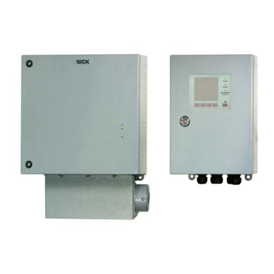
Page 112: Mcu Control Unit
MCU control unit in 19” rack ((shown with Display module option) 465.9 482.6 Name Part No. MCU-NWTD control unit in 19” rack 1046288 MCU-N2RD control unit in 19” rack 1046116 VICOTEC450 · Operating Instructions · 8011767 V 2.3 · © SICK AG... -
Page 113: Optional Connection Box For Connection Cables
Connection box 2046418 Ø 4.8 In stainless steel housing Figure 102 Connection box in stainless steel housing Ø 9 Name Part No. Connection box in stainless steel housing 2048067 VICOTEC450 · Operating Instructions · 8011767 V 2.3 · © SICK AG... -
Page 114: Installation Accessories
Connection cable for VCME to MCU connection, length 50 m 7042019 Fastening sets 7.3.3 Name Part No. Fastening set 4D8-1.4571/PA 2031889 Fastening set 2D4-1.4571/PA 2031890 Fastening set 2M8-1.4571 2031891 Fastening set 4M8-1.4529 2031887 VICOTEC450 · Operating Instructions · 8011767 V 2.3 · © SICK AG... -
Page 115: Options
I/O module carrier 19” (for installation of up to 4 AI/AO and DI/DO modules) 2050589 Interface module 19” Profibus DP 2049334 Interface module 19” Ethernet 2048377 Accessories for device check 7.4.3 Name Part No. Check filter set for VICOTEC450 2043331 VICOTEC450 · Operating Instructions · 8011767 V 2.3 · © SICK AG... -
Page 116: Consumable Parts For 2-Year Operation
7045613 unit) Fuse set T2A 2054541 Control unit Fuse set T2A (for MCU with mains voltage supply) 2054541 Fuse set T4A (for MCU with 24 V supply) 2056334 VICOTEC450 · Operating Instructions · 8011767 V 2.3 · © SICK AG... - Page 117 Specifications VICOTEC450 · Operating Instructions · 8011767 V 2.3 · © SICK AG...
- Page 118 1 (800) 325-7425 – tollfree E-Mail support@sick.jp E-Mail info@sickusa.com Magyarország Phone +36 1 371 2680 E-Mail office@sick.hu Nederlands Phone +31 (0)30 229 25 44 More representatives and agencies at www.sick.com E-Mail info@sick.nl SICK AG | Waldkirch | Germany | www.sick.com...
Need help?
Do you have a question about the VICOTEC450 and is the answer not in the manual?
Questions and answers