
Related Manuals for SICK VMS4400 CV


Summary of Contents for SICK VMS4400 CV
- Page 1 O P E R A T I N G I N S T R U C T IO N S VMS4400 Contour Verification Track and trace systems...
- Page 2 Legal notes This work is protected by copyright. The associated rights are reserved by SICK AG. Reproduction of this document or parts of this document is only permissible within the limits of the legal provisions of copyright law. Any modification, abridgment, or translation of this document is prohibited without the express written permission of SICK AG.
-
Page 3: Table Of Contents
Cleaning the photoelectric retro-reflective sensor ....35 7.1.5 Checking the incremental encoder components ....35 7.1.6 Cleaning the cabinet ..............36 8025816/V1-0/2020-07-06|SICK O P ER A T I NG I NS T R U C T I O NS | VMS4400 Contour Verification Subject to change without notice... - Page 4 Checking the triggering ..............50 8.3.2 Checking the incremental encoder ..........51 Technical data......................52 10 Disposal........................53 O P ER A T I NG I NS T R U C T I O NS | VMS4400 Contour Verification 8025816/V1-0/2020-07-06|SICK Subject to change without notice...
-
Page 5: About This Document
This document describes the multi-dimensional VMS4400 CV measurement system. Target groups This document is intended for qualified persons who operate the VMS4400 CV. 8025816/V1-0/2020-07-06|SICK O P ER A T I NG I NS T R U C T I O NS | VMS4400 Contour Verification... -
Page 6: Further Information
Terminal diagram Operating instructions for the following system components: Operating Instructions Manufacturer LMS4000 2D LiDAR sensor operating instructions SICK Depending on system variant SICK SIM2000 modular system controller SIM Eco modular system controller MSC800 modular system controller... -
Page 7: Safety Information
▸ Follow all local regulations relating to working with electrical components. Only authorized persons are permitted to access the VMS4400 CV. System damage/transport damage Damage to the individual components can lead to malfunctions of the system as a whole. -
Page 8: Requirements For The Qualification Of Personnel
Laser protective cover for the 2D LMS4x21 LiDAR sensor Sources of danger Optical radiation: The VMS4400 CV works with class 2 lasers. Laser class 2 The human eye is not at risk when briefly exposed to the radiation for up to 0.25 seconds. -
Page 9: Warranty
No warranty claims will be accepted if: ▸ The safety notes and measures in this document are not observed. ▸ Parts or components of the VMS4400 CV have been installed, mounted or modified without authorization. ▸ The VMS4400 CV has been altered or modified. -
Page 10: Warning Symbols On The System Components
Read document Use head protection Use foot protection Disconnect before maintenance or repairs O P ER A T I NG I NS T R U C T I O NS | VMS4400 Contour Verification 8025816/V1-0/2020-07-06|SICK Subject to change without notice... -
Page 11: System Description
Aluminum profiles for setting up the frame (application-dependent as per the order) Mounting kits for the cabinet and sensors 8025816/V1-0/2020-07-06|SICK O P ER A T I NG I NS T R U C T I O NS | VMS4400 Contour Verification... -
Page 12: System Components
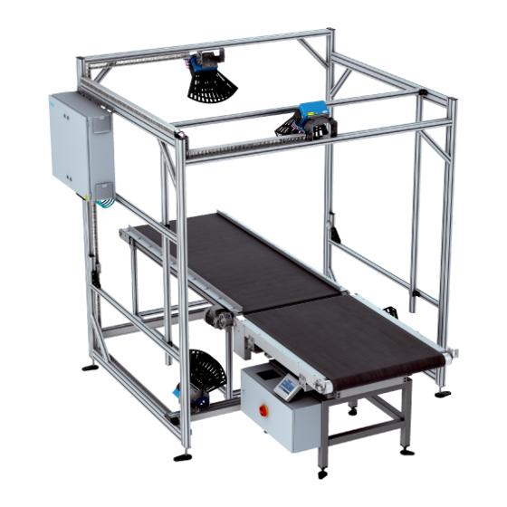
SYSTEM DESCRIPTION System components Devices Fig. 1: Components of the VMS4400 CV Legend 2D LiDAR sensors Photoelectric retro-reflective sensor (optional) Incremental encoder (optional) Cabinet with system controller, dimensioning controller, power supply unit, and Ethernet switch The system components are mounted on a customer-specific frame as per the Mounting technical drawing. -
Page 13: Lms4X21 2D Lidar Sensors
LMS4x21 2D LiDAR sensors Legend LMS4x21 2D LiDAR sensor Laser protective cover The VMS4400 CV comprises four LMS4x21 2D LiDAR sensors with laser protective Features covers. Two 2D LiDAR sensors are mounted below the conveyor belt. The laser scanner beam is guided through the seam between two conveyor belts. -
Page 14: Trigger Photoelectric Sensor
NOTE! Alternatively, the trigger signal can also be supplied by the customer via the PLC. O P ER A T I NG I NS T R U C T I O NS | VMS4400 Contour Verification 8025816/V1-0/2020-07-06|SICK Subject to change without notice... -
Page 15: Incremental Encoder
NOTE! Alternatively, the speed signal can also be supplied by the customer via the controller. 8025816/V1-0/2020-07-06|SICK O P ER A T I NG I NS T R U C T I O NS | VMS4400 Contour Verification Subject to change without notice... -
Page 16: Cabinet
Dimensioning controller (example in the image: APU8520) Ethernet switch Air inlet for cooling (with filter mat and fan) O P ER A T I NG I NS T R U C T I O NS | VMS4400 Contour Verification 8025816/V1-0/2020-07-06|SICK Subject to change without notice... - Page 17 8025816/V1-0/2020-07-06|SICK O P ER A T I NG I NS T R U C T I O NS | VMS4400 Contour Verification Subject to change without notice...
-
Page 18: Operating Principle
Objects are singulated by the customer. The objects must pass the VMS4400 CV with a defined separation distance larger than the max. object height (distance between rear edge and leading edge). The minimum distance must ensure that there is always only one object in the measuring range. - Page 19 The objects must not be touching * Otherwise the track and trace system will not deliver plausible measurement results. 8025816/V1-0/2020-07-06|SICK O P ER A T I NG I NS T R U C T I O NS | VMS4400 Contour Verification...
-
Page 20: Recording Of Measured Values And Data Processing
Recording of measured values and data processing Fig. 8: Measuring point determination of the VMS4400 CV The measurement process is activated via the trigger signal. The two 2D LiDAR sensors mounted below and above the conveying equipment span a two-dimensional measuring range and perform a non-contact scan of the surface of the object on the conveying equipment. - Page 21 The distance value between the recorded contour and the ideal contour of the enclosing cuboid determines the extent of the deformation. The VMS4400 CV does not differentiate between dents and bulges. The change in dimension based on the volume of the smallest enclosing cuboid is interpreted simply as an object deformation.
- Page 22 We recommend specifying dimensions no smaller than 22 mm. O P ER A T I NG I NS T R U C T I O NS | VMS4400 Contour Verification 8025816/V1-0/2020-07-06|SICK Subject to change without notice...
-
Page 23: Data Output
SYSTEM DESCRIPTION 3.3.3 Data output Fig. 12: Data output of the VMS4400 CV Legend Data output via Ethernet Data output via fieldbus or Profibus (controller-dependent) Data output via RS-232 / RS422 The system controller receives the measurement results from the deformation check of the dimensioning controller and assigns the calculated measurement and deformation results to the relevant object. -
Page 24: Expanding The System With A Reading And Weighing Station
The weight, together with the bar code and the calculated volume, are transmitted for the purpose of controlling the goods and material flow. The devices are connected to the VMS4400 CV via the system controller. Connection The controller links the acquired identification and weight data with the dimensional values calculated by the VMS4400 CV. -
Page 25: System Requirements
Any conditions outside the limits will lead to problems or a reduction in measurement accuracy. 3.4.1 Requirements on the ambient conditions The operation site of the VMS4400 CV must have the following features: Closed or covered room Flat and firm surface Low-vibration environment ... -
Page 26: Requirements On The Conveying Equipment
Object color Radiance factor [%] Black cardboard Blue White Black with shiny tape O P ER A T I NG I NS T R U C T I O NS | VMS4400 Contour Verification 8025816/V1-0/2020-07-06|SICK Subject to change without notice... -
Page 27: Mounting Requirements
No side guards are to be mounted in the vicinity of the scan lines. 8025816/V1-0/2020-07-06|SICK O P ER A T I NG I NS T R U C T I O NS | VMS4400 Contour Verification... -
Page 28: Mounting
The track and trace system is mounted by the manufacturer. This is not covered in these operating instructions. O P ER A T I NG I NS T R U C T I O NS | VMS4400 Contour Verification 8025816/V1-0/2020-07-06|SICK Subject to change without notice... -
Page 29: Electrical Installation
All connection work is carried out by the manufacturer. It is not covered in these operating instructions. 8025816/V1-0/2020-07-06|SICK O P ER A T I NG I NS T R U C T I O NS | VMS4400 Contour Verification Subject to change without notice... - Page 30 ELECTRICAL INSTALLATION Connection overview Fig. 16: Connection overview for the VMS4400 CV 2D LiDAR sensor (master) CAN bus Ethernet CAN bus Increment and synchronization 2D LiDAR sensor (slave) CAN bus Ethernet Synchronization 2D LiDAR sensor (master) CAN bus Ethernet Synchronization...
-
Page 31: Commissioning
LMS4x21 master 192.168.0.12 LMS4x21 slave 192.168.0.13 Tab. 2: Recommended addresses of device components 8025816/V1-0/2020-07-06|SICK O P ER A T I NG I NS T R U C T I O NS | VMS4400 Contour Verification Subject to change without notice... -
Page 32: Maintenance And Repair
Control measurements with test objects to check Whenever the Trained General system is started personnel the measurement accuracy of the VMS4400 CV Visual inspection of the electrical cabling and wiring Trained 1x/year for damage personnel Service Maintenance of the individual components... -
Page 33: Monitoring And Cleaning Work
▸ Ensure proper functioning of the VMS4400 CV by means of regular testing. ▸ To do so, check the measurement accuracy of the VMS4400 CV using defined reference objects (see below). ▸ If any unexpected deviations are found, check the system for mechanical damage. -
Page 34: Cleaning The 2D Lidar Sensors
WARNING! HAZARDOUS LASER RADIATION The VMS4400 CV works with class 2 lasers. The human eye is not at risk when briefly exposed to the radiation for up to 0.25 seconds. Exposure to the laser beam for longer periods of time may cause damage to the retina. -
Page 35: Cleaning The Photoelectric Retro-Reflective Sensor
NOTE! If it is so badly worn that contact with the conveyor belt is impaired, the incremental encoder must be replaced (see below). 8025816/V1-0/2020-07-06|SICK O P ER A T I NG I NS T R U C T I O NS | VMS4400 Contour Verification... -
Page 36: Cleaning The Cabinet
Reattach the covers the right way up and press them down until they click into place. O P ER A T I NG I NS T R U C T I O NS | VMS4400 Contour Verification 8025816/V1-0/2020-07-06|SICK Subject to change without notice... -
Page 37: Replacing Components
Current national regulations regarding laser protection must be observed. WARNING RISK OF DEVICE DAMAGE ▸ Disconnect the power to the VMS4400 CV before carrying out maintenance work. Removing a defective device Fig. 21: Removing the 2D LiDAR sensor from the mounting plate ▸... - Page 38 NOTE! It may be necessary to recalibrate the exchanged 2D LiDAR sensor using SOPAS. O P ER A T I NG I NS T R U C T I O NS | VMS4400 Contour Verification 8025816/V1-0/2020-07-06|SICK Subject to change without notice...
-
Page 39: Replacing The System Controller
Plug the Ethernet cables into the designated connectors. Select the same position for the microswitch as in the removed system controller. 8025816/V1-0/2020-07-06|SICK O P ER A T I NG I NS T R U C T I O NS | VMS4400 Contour Verification... -
Page 40: Replacing The Battery In The System Controller
Set the system time again using the SOPAS software (Project tree MSC800 System REAL-TIME CLOCK area). O P ER A T I NG I NS T R U C T I O NS | VMS4400 Contour Verification 8025816/V1-0/2020-07-06|SICK Subject to change without notice... -
Page 41: Replacing The Dimensioning Controller
USB stick. Check that the power LED is lit up green. 8025816/V1-0/2020-07-06|SICK O P ER A T I NG I NS T R U C T I O NS | VMS4400 Contour Verification... -
Page 42: Replacing The Power Supply Unit
Mounting strap Input voltage connection Potentiometer for the output voltage Output voltage connection O P ER A T I NG I NS T R U C T I O NS | VMS4400 Contour Verification 8025816/V1-0/2020-07-06|SICK Subject to change without notice... - Page 43 Set the output voltage on the power supply module to 26 V using the potentiometer. ▸ Check that the output voltage is correct. 8025816/V1-0/2020-07-06|SICK O P ER A T I NG I NS T R U C T I O NS | VMS4400 Contour Verification Subject to change without notice...
-
Page 44: Replacing The Photoelectric Retro-Reflective Sensor
Check that the photoelectric retro-reflective sensor is operating correctly. O P ER A T I NG I NS T R U C T I O NS | VMS4400 Contour Verification 8025816/V1-0/2020-07-06|SICK Subject to change without notice... -
Page 45: Replacing The Incremental Encoder Components
▸ Screw the M12 plug connector onto the male connector on the incremental encoder. 8025816/V1-0/2020-07-06|SICK O P ER A T I NG I NS T R U C T I O NS | VMS4400 Contour Verification Subject to change without notice... -
Page 46: Fault Diagnosis
If you cannot remedy the fault with the help of the information provided in this chapter, SICK support please contact your local SICK subsidiary. O P ER A T I NG I NS T R U C T I O NS | VMS4400 Contour Verification... -
Page 47: Fault Indications Of The Components
▸ Check the device status using SOPAS (see below). ▸ If errors are listed there, contact SICK Service. Tab. 4: Fault indication on the 2D LiDAR sensor 8025816/V1-0/2020-07-06|SICK O P ER A T I NG I NS T R U C T I O NS | VMS4400 Contour Verification... -
Page 48: Fault Indication On The System Controller
Replace the 2D LiDAR sensor. Tab. 5: Fault indication on the system controller O P ER A T I NG I NS T R U C T I O NS | VMS4400 Contour Verification 8025816/V1-0/2020-07-06|SICK Subject to change without notice... -
Page 49: Fault Indication On The Trigger Photoelectric Retro-Reflective Sensor
Tab. 6: Fault indication on the trigger photoelectric retro-reflective sensor (e.g., WL27-3) 8025816/V1-0/2020-07-06|SICK O P ER A T I NG I NS T R U C T I O NS | VMS4400 Contour Verification Subject to change without notice... -
Page 50: Fault Indication During Operation
Replace the device. defective. Tab. 7: Check the triggering on the system controller O P ER A T I NG I NS T R U C T I O NS | VMS4400 Contour Verification 8025816/V1-0/2020-07-06|SICK Subject to change without notice... -
Page 51: Checking The Incremental Encoder
Replace the device. Tab. 8: Checking the incremental signals on the system controller 8025816/V1-0/2020-07-06|SICK O P ER A T I NG I NS T R U C T I O NS | VMS4400 Contour Verification Subject to change without notice... -
Page 52: Technical Data
Higher speeds on request For cubic objects Tab. 9: Technical data of the VMS4400 CV O P ER A T I NG I NS T R U C T I O NS | VMS4400 Contour Verification 8025816/V1-0/2020-07-06|SICK Subject to change without notice... -
Page 53: Disposal
The following assemblies may contain substances that need to be disposed of separately: Electronics: Capacitors, accumulators, batteries. Displays: Liquid in the LC displays. 8025816/V1-0/2020-07-06|SICK O P ER A T I NG I NS T R U C T I O NS | VMS4400 Contour Verification Subject to change without notice... - Page 54 Phone +36 1 371 2680 Phone +386 591 78849 E-Mail ertekesites@sick.hu E-Mail office@sick.si India South Africa Phone +91-22-6119 8900 Phone +27 (0)11 472 3733 E-Mail info@sick-india.com E-Mail info@sickautomation.co.za Further locations at www.sick.com SICK AG | Waldkirch | Germany | www.sick.com...
Need help?
Do you have a question about the VMS4400 CV and is the answer not in the manual?
Questions and answers