
Related Manuals for SICK MARSIC200


Summary of Contents for SICK MARSIC200
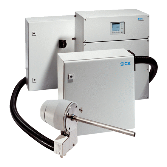
- Page 1 T E C H N I C A L I N F O R M A T I O N MARSIC200 Ship Emission Measuring Device Installation and Initial Start-up...
- Page 2 Original document This document is an original document of SICK AG. T E C H N I C A L I N F O R M A T I O N | MARSIC200 8017324/15A2/V6-0/2019-10 | SICK Subject to change without notice...
-
Page 3: Table Of Contents
2.11.3 Electrical installation of analyzer..........Initial start-up..................36 Initial start-up.................... 8017324/15A2/V6-0/2019-10 | SICK T E C H N I C A L I N F O R M A T I O N | MARSIC200 Subject to change without notice... - Page 4 7.10 Emissions....................7.11 Torques for screw fittings................. 7.12 Tube connections..................T E C H N I C A L I N F O R M A T I O N | MARSIC200 8017324/15A2/V6-0/2019-10 | SICK Subject to change without notice...
- Page 5 CONTENTS 7.13 Sample gas conditions................8017324/15A2/V6-0/2019-10 | SICK T E C H N I C A L I N F O R M A T I O N | MARSIC200 Subject to change without notice...
-
Page 6: About This Document
Table 1: Warning symbols Symbol Significance Hazard (general) Hazard by voltage T E C H N I C A L I N F O R M A T I O N | MARSIC200 8017324/15A2/V6-0/2019-10 | SICK Subject to change without notice... -
Page 7: Warning Levels / Signal Words
Important technical information for this product Important information on electric or electronic functions 8017324/15A2/V6-0/2019-10 | SICK T E C H N I C A L I N F O R M A T I O N | MARSIC200 Subject to change without notice... -
Page 8: Installation
Zero point gas Nitrogen 5.0 Max. +300 hPa Typically 60 l/h T E C H N I C A L I N F O R M A T I O N | MARSIC200 8017324/15A2/V6-0/2019-10 | SICK Subject to change without notice... -
Page 9: Tube Screw Fitting
(the resistance increases noticeably) and then slightly tighten. 8017324/15A2/V6-0/2019-10 | SICK T E C H N I C A L I N F O R M A T I O N | MARSIC200 Subject to change without notice... -
Page 10: Scope Of Delivery
Nitrogen or instrument air as zero gas: Observe the required quality: see "Sample gas conditions", page 66 T E C H N I C A L I N F O R M A T I O N | MARSIC200 8017324/15A2/V6-0/2019-10 | SICK Subject to change without notice... -
Page 11: Installation Overview
• Power supply of the sampling probe • Signal line 8017324/15A2/V6-0/2019-10 | SICK T E C H N I C A L I N F O R M A T I O N | MARSIC200 Subject to change without notice... - Page 12 Test gas connection during adjustment Condensate outlet ä Signal lines/Ethernet to periphery å T E C H N I C A L I N F O R M A T I O N | MARSIC200 8017324/15A2/V6-0/2019-10 | SICK Subject to change without notice...
-
Page 13: System Layout For 1
Signal (7x1.5; Order no: 6056230) Yellow PTFE line (4/6; Order no: 5310243) 8017324/15A2/V6-0/2019-10 | SICK T E C H N I C A L I N F O R M A T I O N | MARSIC200 Subject to change without notice... - Page 14 Signal (7x1.5; Order no: 6056230) Yellow PTFE line (4/6; Order no: 5310243) T E C H N I C A L I N F O R M A T I O N | MARSIC200 8017324/15A2/V6-0/2019-10 | SICK Subject to change without notice...
-
Page 15: Checklist For Mechanical And Electrical Installation
2.9.2 ä Numbering see "Installation overview", page 11 8017324/15A2/V6-0/2019-10 | SICK T E C H N I C A L I N F O R M A T I O N | MARSIC200 Subject to change without notice... -
Page 16: Lay And Connect The Electric Lines Between Sampling Probe With Sample Conditioning And Distribution Unit
Line 3 Line 2 Line 1 Figure 3: Wiring diagram T E C H N I C A L I N F O R M A T I O N | MARSIC200 8017324/15A2/V6-0/2019-10 | SICK Subject to change without notice... - Page 17 Marine Line (3x1,5) 6056215 Line 1 Figure 4: Wiring diagram 8017324/15A2/V6-0/2019-10 | SICK T E C H N I C A L I N F O R M A T I O N | MARSIC200 Subject to change without notice...
- Page 18 Sampling probe: see chapter 2.7 Sample conditioning: see chapter 2.9.3 T E C H N I C A L I N F O R M A T I O N | MARSIC200 8017324/15A2/V6-0/2019-10 | SICK Subject to change without notice...
-
Page 19: Lay And Connect The Electric Line Between Distribution Unit And Analyzer
External Power supply supplyes by customer Figure 5: Wiring diagram 8017324/15A2/V6-0/2019-10 | SICK T E C H N I C A L I N F O R M A T I O N | MARSIC200 Subject to change without notice... - Page 20 External Power supply supplyes by customer Figure 6: Wiring diagram T E C H N I C A L I N F O R M A T I O N | MARSIC200 8017324/15A2/V6-0/2019-10 | SICK Subject to change without notice...
-
Page 21: Installing The Sampling Probe
Fit the sampling tube with the probe tip tilted down about 10°. min.70 10° 8017324/15A2/V6-0/2019-10 | SICK T E C H N I C A L I N F O R M A T I O N | MARSIC200 Subject to change without notice... -
Page 22: Installing The Sample Gas Line
Observe the laying instructions for the sample gas line (enclosed with the sample gas line). T E C H N I C A L I N F O R M A T I O N | MARSIC200 8017324/15A2/V6-0/2019-10 | SICK... - Page 23 The line marked blue on the solenoid valve KK10, connection “A”. 8017324/15A2/V6-0/2019-10 | SICK T E C H N I C A L I N F O R M A T I O N | MARSIC200 Subject to change without notice...
-
Page 24: Installing The Sample Conditioning
Sample gas cooler with hose pump Cooler sample gas inlet (inlet of heated sample gas line) T E C H N I C A L I N F O R M A T I O N | MARSIC200 8017324/15A2/V6-0/2019-10 | SICK... -
Page 25: Gas Connections On Sample Conditioning
2.9.2 Gas connections on sample conditioning Overview of connection positions 8017324/15A2/V6-0/2019-10 | SICK T E C H N I C A L I N F O R M A T I O N | MARSIC200 Subject to change without notice... - Page 26 The condensate outlet is at the bottom of the cooler. Acid condensate escapes from the condensate outlet. T E C H N I C A L I N F O R M A T I O N | MARSIC200 8017324/15A2/V6-0/2019-10 | SICK...
-
Page 27: Electrical Installation Of Sample Conditioning
Figure 11: Distribution unit (interior view sys‐ Figure 10: Distribution unit (exterior view) tem-specific) 8017324/15A2/V6-0/2019-10 | SICK T E C H N I C A L I N F O R M A T I O N | MARSIC200 Subject to change without notice... - Page 28 The analyzer signals the flow is too low when the filter clogs Sample gas outlet to ana‐ ß lyzer T E C H N I C A L I N F O R M A T I O N | MARSIC200 8017324/15A2/V6-0/2019-10 | SICK Subject to change without notice...
-
Page 29: Fitting The Distribution Unit
Observe the relevant ambient conditions: see "Technical data", page ° 8017324/15A2/V6-0/2019-10 | SICK T E C H N I C A L I N F O R M A T I O N | MARSIC200 Subject to change without notice... -
Page 30: Gas Connections On Distribution Unit
(not via the sampling probe), the span gas must be connected to this inlet during the adjustment. T E C H N I C A L I N F O R M A T I O N | MARSIC200 8017324/15A2/V6-0/2019-10 | SICK... -
Page 31: Electrical Installation Of Distribution Unit
Observe the max. power input of the complete system: see "Energy supply", page 8017324/15A2/V6-0/2019-10 | SICK T E C H N I C A L I N F O R M A T I O N | MARSIC200 Subject to change without notice... -
Page 32: Measuring Point Switchover
Programming the measuring point switchover: see "Measuring points - automatic", page T E C H N I C A L I N F O R M A T I O N | MARSIC200 8017324/15A2/V6-0/2019-10 | SICK Subject to change without notice... -
Page 33: Installing The Analyzer
Measuring module SO (DEFOR) à Measuring module flow/humidity/pressure (gas á module) 8017324/15A2/V6-0/2019-10 | SICK T E C H N I C A L I N F O R M A T I O N | MARSIC200 Subject to change without notice... -
Page 34: Fitting The Analyzer
Lay all PTFE tubes into the enclosure from the bottom. Connect the lines. T E C H N I C A L I N F O R M A T I O N | MARSIC200 8017324/15A2/V6-0/2019-10 | SICK Subject to change without notice... -
Page 35: Electrical Installation Of Analyzer
The green coiled network line in the analyzer bottom part serves as spare line and does not have to be connected. 8017324/15A2/V6-0/2019-10 | SICK T E C H N I C A L I N F O R M A T I O N | MARSIC200 Subject to change without notice... -
Page 36: Initial Start-Up
17. Perform the leak tightness check: See “Operating Instructions MARSIC200”. ✓ The system is in operation. T E C H N I C A L I N F O R M A T I O N | MARSIC200 8017324/15A2/V6-0/2019-10 | SICK Subject to change without notice... - Page 37 To do this, connect the analyzer to a PC and use the SICK SOPAS-ET software (see "Backup of settings", page 53). 8017324/15A2/V6-0/2019-10 | SICK T E C H N I C A L I N F O R M A T I O N | MARSIC200 Subject to change without notice...
-
Page 38: Configuration Software
User level Password (case-sensitive) MARSIC Authorized operator HIDE Service hidden T E C H N I C A L I N F O R M A T I O N | MARSIC200 8017324/15A2/V6-0/2019-10 | SICK Subject to change without notice... -
Page 39: Adjustment Functions
Deactivate Live view. Select the desired Table rows. Select Edit. 8017324/15A2/V6-0/2019-10 | SICK T E C H N I C A L I N F O R M A T I O N | MARSIC200 Subject to change without notice... - Page 40 Simultaneous use for zero point validations or reference point validations with adjustment cuvette is not possible. T E C H N I C A L I N F O R M A T I O N | MARSIC200 8017324/15A2/V6-0/2019-10 | SICK...
-
Page 41: Performing A Manual Adjustment
Alternative (when a further manual adjustment is to follow): The test gas for the next manual adjust 8017324/15A2/V6-0/2019-10 | SICK T E C H N I C A L I N F O R M A T I O N | MARSIC200 Subject to change without notice... - Page 42 Name of countdown timer running Remaining time Remaining time of countdown timer running T E C H N I C A L I N F O R M A T I O N | MARSIC200 8017324/15A2/V6-0/2019-10 | SICK Subject to change without notice...
- Page 43 á Internal interval for computation of the values measured â 8017324/15A2/V6-0/2019-10 | SICK T E C H N I C A L I N F O R M A T I O N | MARSIC200 Subject to change without notice...
-
Page 44: Automatic Adjustments/Validations
Error shown when no result available. Erroneous sequence or drift overrun. The actual measured value measured Automatic adjustments/validations T E C H N I C A L I N F O R M A T I O N | MARSIC200 8017324/15A2/V6-0/2019-10 | SICK Subject to change without notice... -
Page 45: Function Of Automatic Adjustments/Validations
Deactivate Live view. Select the desired Table rows. Select Edit. 8017324/15A2/V6-0/2019-10 | SICK T E C H N I C A L I N F O R M A T I O N | MARSIC200 Subject to change without notice... - Page 46 The procedure first has the status completed after this flush time. Starts immediately after the end of this procedure. T E C H N I C A L I N F O R M A T I O N | MARSIC200 8017324/15A2/V6-0/2019-10 | SICK...
-
Page 47: Tests And Settings
Select the digital output to be tested and click “Test”. A LED (green) is on when the selected digital input is active. 8017324/15A2/V6-0/2019-10 | SICK T E C H N I C A L I N F O R M A T I O N | MARSIC200 Subject to change without notice... -
Page 48: Digital Outputs
If relay outputs do not function, the I/O modules must be exchanged because they can‐ not be repaired onsite. T E C H N I C A L I N F O R M A T I O N | MARSIC200 8017324/15A2/V6-0/2019-10 | SICK... -
Page 49: Analog Outputs
Analog inputs and/or analog outputs must then be adapted. Tools required Ammeter Constant current source or analog output 8017324/15A2/V6-0/2019-10 | SICK T E C H N I C A L I N F O R M A T I O N | MARSIC200 Subject to change without notice... -
Page 50: Setting Analog Interfaces
Configuring measured values Procedure Menu: Call up BCU/Parameter/Measured values (MVi). T E C H N I C A L I N F O R M A T I O N | MARSIC200 8017324/15A2/V6-0/2019-10 | SICK Subject to change without notice... - Page 51 Formula for assignment or calculation of the measured value ß Limit value à 8017324/15A2/V6-0/2019-10 | SICK T E C H N I C A L I N F O R M A T I O N | MARSIC200 Subject to change without notice...
-
Page 52: Measuring Points - Automatic
Digital outputs for measuring points automatic are controlled using tag MPiS (see “Technical Information BCU”). T E C H N I C A L I N F O R M A T I O N | MARSIC200 8017324/15A2/V6-0/2019-10 | SICK... -
Page 53: Configuring Measuring Point Automatic
This means only the last two backups are saved. 8017324/15A2/V6-0/2019-10 | SICK T E C H N I C A L I N F O R M A T I O N | MARSIC200 Subject to change without notice... - Page 54 Select a user level and enter the associated password. All parameters that can be modified with the selected user level are overwritten. T E C H N I C A L I N F O R M A T I O N | MARSIC200 8017324/15A2/V6-0/2019-10 | SICK...
-
Page 55: Technical Data
Observe clearances: • Bottom: 20 cm • Right: 30 cm 8017324/15A2/V6-0/2019-10 | SICK T E C H N I C A L I N F O R M A T I O N | MARSIC200 Subject to change without notice... -
Page 56: Dimensional Drawing Of Distribution Unit
Dimensional drawing of distribution unit Ø 10 NOTICE Observe clearance: • Bottom: 20 cm T E C H N I C A L I N F O R M A T I O N | MARSIC200 8017324/15A2/V6-0/2019-10 | SICK Subject to change without notice... -
Page 57: Dimensional Drawing Of Analyzer
Observe clearance: • Right: 10 cm • Bottom: 20 cm 8017324/15A2/V6-0/2019-10 | SICK T E C H N I C A L I N F O R M A T I O N | MARSIC200 Subject to change without notice... -
Page 58: Dimensional Drawing Of Sampling Probe
Sample gas line, heated Figure 35: Technical drawing - heated sample gas line T E C H N I C A L I N F O R M A T I O N | MARSIC200 8017324/15A2/V6-0/2019-10 | SICK Subject to change without notice... -
Page 59: Gas Flow Diagram
SINGLE version distribution unit for one measuring point Figure 36: Gas flow diagram 8017324/15A2/V6-0/2019-10 | SICK T E C H N I C A L I N F O R M A T I O N | MARSIC200 Subject to change without notice... - Page 60 MULTI version distribution unit for two to four measuring points Figure 37: Gas flow diagram T E C H N I C A L I N F O R M A T I O N | MARSIC200 8017324/15A2/V6-0/2019-10 | SICK...
-
Page 61: Measuring Parameters
Air pressure 900 ... 1100 hPa Degree of protection IP 54 8017324/15A2/V6-0/2019-10 | SICK T E C H N I C A L I N F O R M A T I O N | MARSIC200 Subject to change without notice... -
Page 62: Sample Gas Conditions
Sample conditioning: IP54 • Distribution unit: IP54 • Analyzer: IP54 T E C H N I C A L I N F O R M A T I O N | MARSIC200 8017324/15A2/V6-0/2019-10 | SICK Subject to change without notice... -
Page 63: Sample Gas Line, Heated
Highest allowable input signal 30 mA Overcurrent protective device ±1000 mA 8017324/15A2/V6-0/2019-10 | SICK T E C H N I C A L I N F O R M A T I O N | MARSIC200 Subject to change without notice... -
Page 64: Energy Supply
10 A 20 A 3200 VA 14 A 28 A T E C H N I C A L I N F O R M A T I O N | MARSIC200 8017324/15A2/V6-0/2019-10 | SICK Subject to change without notice... -
Page 65: Emissions
3 Nm Complete analyzer module, 7 black 9 Nm screws 8017324/15A2/V6-0/2019-10 | SICK T E C H N I C A L I N F O R M A T I O N | MARSIC200 Subject to change without notice... -
Page 66: Tube Connections
(e.g., MARPOL Annex VI) T E C H N I C A L I N F O R M A T I O N | MARSIC200 8017324/15A2/V6-0/2019-10 | SICK Subject to change without notice... - Page 67 TECHNICAL DATA 8017324/15A2/V6-0/2019-10 | SICK T E C H N I C A L I N F O R M A T I O N | MARSIC200 Subject to change without notice...
- Page 68 E-Mail office@sick.com.gr E-Mail info@sick.ru Vietnam Hong Kong Singapore Phone +65 6744 3732 Phone +852 2153 6300 Phone +65 6744 3732 E-Mail sales.gsg@sick.com E-Mail ghk@sick.com.hk E-Mail sales.gsg@sick.com Detailed addresses and further locations at www.sick.com SICK AG | Waldkirch | Germany | www.sick.com...
Need help?
Do you have a question about the MARSIC200 and is the answer not in the manual?
Questions and answers