Table of Contents
Advertisement
Advertisement
Table of Contents

Related Manuals for SICK LFP CUBIC


Summary of Contents for SICK LFP CUBIC
- Page 1 O P E R A T I N G I N S T R U C T I O N S LFP CUBIC TDR level sensor...
- Page 2 79183 Waldkirch, Germany Germany Legal notices This work is protected by copyright. The associated rights are reserved by SICK AG. Reproduction of this document or parts of this document is only permissible within the limits of the legal determination of Copyright Law.
-
Page 3: Table Of Contents
Contents About this document ..................6 Information on the operating instructions ..............6 Scope .......................... 6 Explanation of symbols ....................6 Further information ....................7 Customer service ......................7 Safety information ...................8 Intended use ....................... 8 Incorrect use ....................... 8 Limitation of liability ....................8 Modifications and conversions .................. - Page 4 Electrical installation ..................21 Safety ........................21 6.1.1 Notes on the electrical installation ............21 Electrical connection ....................22 6.2.1 Overview of the electrical connections ...........22 6.2.2 Pin assignment, M12 plug connector, 5-pin ...........22 6.2.3 Pin assignment, M12 plug connector, 8-pin ...........23 Commissioning ....................24 Quick commissioning (with factory settings) ............24 Advanced commissioning ..................24 Foam commissioning (with factory settings) ............26...
- Page 5 Menu overview ....................45 Overview of parameters ................48 Troubleshooting ..................... 52 11.1 Error message on the display ..................52 11.2 Operating the display ....................53 11.3 Outputs........................54 11.4 Error behavior ......................54 Repair work ....................55 12.1 Maintenance ......................55 12.2 Returns ........................55 Disposal ......................
-
Page 6: About This Document
ABOUT THIS DOCUMENT About this document Information on the operating instructions These operating instructions provide important notes on how to use sensors from SICK AG. Prerequisites for safe work are: • Compliance with all safety notes and handling instructions supplied. -
Page 7: Further Information
NOTE All the documentation available for the sensor can be found on the online product page at: www.sick.com The following information is available for download there: • Model-specific online data sheets for device variants, containing technical data, dimensional drawings and diagrams •... -
Page 8: Safety Information
Interrupting or modifying the sensor or SICK software will invalidate any warranty claims against SICK AG. This applies in particular to opening the housing, even as part of mounting and electrical installation. Before technical modifications to and expansions of the sensor, the prior written approval of the manufacturer must be obtained. -
Page 9: Requirements For Skilled Persons And Operating Personnel
SAFETY INFORMATION Requirements for skilled persons and operating personnel WARNING Risk of injury due to insufficient training. Improper handling of the sensor may result in considerable personal injury and material damage. • All work must only ever be carried out by the stipulated persons. The operating instructions state the following qualification requirements for the various areas of work: •... -
Page 10: General Safety Notes
Repairs Repair work on the sensor may be performed only by qualified and authorized personnel from SICK AG. Interruptions or modifications to the sensor on the part of the customer will invalidate any warranty claims against SICK AG. O P E R A T I N G I N S T R U C T I O N S | L F P C U B I C... -
Page 11: Product Description
PRODUCT DESCRIPTION Product description Product ID 3.1.1 Information on the housing There is information printed on the housing identifying the sensor and its electrical connection. 3.1.2 Type code Position Description Product group LFP (level sensors) Probe length in mm 0025: without probe 0200: in 10 mm increments;... -
Page 12: Product Characteristics
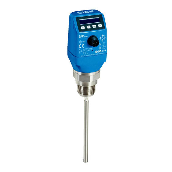
PRODUCT DESCRIPTION Product characteristics 3.2.1 Device view Fig. 1: LFP Cubic (standard version) 1 Sample probe 2 Electrical connection 3 Operating buttons 4 Display 3.2.2 Operating buttons The sensor is operated using the display and operating buttons. For a detailed description of the pushbuttons and their functions, see “8.1 Display and... -
Page 13: Fields Of Application
PRODUCT DESCRIPTION 3.3.2 Fields of application The innovative TDR technology enables reliable level measurement which is largely application-independent. The LFP is suitable for both continuous level measurement and point level measurement in nearly all liquids. The sensor is not affected by changes in the properties of the liquids to be measured. The LFP can be used in metal containers or bypass/immersion pipes. -
Page 14: Transport And Storage
TRANSPORT AND STORAGE Transport and storage Transport For your own safety, please read and observe the following notes: IMPORTANT Damage to the sensor due to improper transport. • The device must be packaged for transport with protection against shock and damp. •... -
Page 15: Mounting
5.1.1 Installation in a container Note: The distances are identical for the sensor with remote amplifier. Fig. 2: LFP Cubic Mono-probe with metallic containers Coaxial tube in metallic and non-metallic containers Installation in the nozzle C = In the case of a coaxial probe there D ≥... -
Page 16: Installation In A Metal Immersion Tube Or Metal Bypass
MOUNTING 5.1.2 Installation in a metal immersion tube or metal bypass Fig. 3: LFP Cubic Centering D ≥ DN 40 Distance to bypass/container bottom B ≥ 10 mm Centering: To prevent contact between the probe and the bypass pipe during oscillations, the probe should be centered according to its length and depending on the diameter of the bypass pipe. -
Page 17: Rope Probe In The Metallic Container
MOUNTING 5.1.3 Rope probe in the metallic container Fig. 4: LFP Cubic Rope weight Bracket rope tension Installation in the nozzle: D ≥ DN 25 Container wall/container bottom distance: A ≥ 50 mm Distance from components built into container: ≥ 100 mm... -
Page 18: Mounting The Coaxial Tube
MOUNTING Mounting the coaxial tube See the operating instructions for the coaxial tube (8015674) at www.sick.com. Shortening or replacing the probe rod/rope probe If the probe rod or rope probe is too long for the application, it can be shortened to the container height. -
Page 19: Shortening The Rope Probe
MOUNTING 5.3.2 Shortening the rope probe 2 mm hexagon screw Loosen the setscrews (3x) Rope weight New probe length Shift the rope weight to the desired length Setscrews* (tighten according to desired length 1.5 Nm, 3x) *It is recommended that the setscrews be secured with a thread-locking lacquer 8019918 /ZJA6/ 2017-07-20 | S I C K A G O P E R A T I N G I N S T R U C T I O N S | L F P C U B I C Subject to change without notice... -
Page 20: Mounting The Probe Rod
MOUNTING Mounting the probe rod With the LFP Cubic, the probe rod can be modified by the customer. The specifications for the probe rod should be as follows: Probe rod diameter: 7 mm … 8 mm Female thread on the probe rod: M5 Female thread length: min. -
Page 21: Electrical Installation
ELECTRICAL INSTALLATION Electrical installation Safety 6.1.1 Notes on the electrical installation IMPORTANT Equipment damage due to incorrect supply voltage! An incorrect supply voltage may result in damage to the equipment. • Only operate the device using a protected low voltage and safe electrical insulation as per protection class III. -
Page 22: Electrical Connection
Once installed, the sensor is ready for operation upon completion of the self-test (< 5 s). The display shows the current measured value. Fig. 5: LFP Cubic 6.2.2 Pin assignment, M12 plug connector, 5-pin Fig. 6: M12 x 1 plug connector, 5-pin... -
Page 23: Pin Assignment, M12 Plug Connector, 8-Pin
ELECTRICAL INSTALLATION 6.2.3 Pin assignment, M12 plug connector, 8-pin Fig. 7: M12 x 1 plug connector, 8-pin Contact Marking Description Supply voltage Switching output 2, PNP/ NPN Ground, reference potential for current/voltage output Switching output 1, PNP/IO-Link communication Switching output 3, PNP/NPN Switching output 4, PNP/NPN Analog current/voltage output No function... -
Page 24: Commissioning
“18 Media list”. • There are tank components which can interfere with the measurement signal (in the case of the LFP Cubic). • In the event of significant ripples in the surface of the liquid. • If there are variations in the installation conditions, see “5... - Page 25 COMMISSIONING Commissioning Mount the sensor in accordance with the installation conditions, see “5 Mounting”. Log in to expert mode, see “8.4.1 Expert mode”. Select the measuring mode. • Access the EXPRT-CONFIG-MeasMd menu using the arrow and Set pushbuttons. • HiSpd: max. length = 2005 mm, response time < 400 ms. •...
-
Page 26: Foam Commissioning (With Factory Settings)
COMMISSIONING Note: • Use the foam commissioning instructions for applications with foam. • The sensor automatically quits expert mode after 5 minutes of inactivity on the display. • Any of the following processes voids the configuration (AutCal): • Changing the probe length •... - Page 27 COMMISSIONING Note: • Measurement deviation can be higher. • Signal quality 1 and 2 are not counted. • The sensor automatically quits expert mode after 5 minutes of inactivity on the display. • Configuration (foam teach) does not take place in the following processes: •...
-
Page 28: Operation
For operation over IO-Link, an IODD file and a description of the available telegram parameters are available for download at www.sick.com. O P E R A T I N G I N S T R U C T I O N S | L F P C U B I C... -
Page 29: Configuring The Switching Outputs
OPERATION Configuring the switching outputs 8.2.1 Switching hysteresis and window function Depending on 2 or 4 output variants Level If the level is fluctuating around the target value (e.g. ripple movement during filling), the hysteresis keeps the switching status of the outputs stable. When the level is increasing, the output switches when the respective high... -
Page 30: Normally Open With Adjustable Hysteresis
OPERATION 8.2.2 Normally open with adjustable hysteresis Applications • Dry run protection • Empty signal Configuration Configure the Qx switching output as normally open. • Set the parameter in the QxMENU-OUx menu to Qx_Hno. Set the switching point. • Set the value in the QxMENU-SPx menu to the level in mm (e.g. 500 mm). Set the reset point. -
Page 31: N/C Output With Configurable Hysteresis
OPERATION 8.2.3 N/C output with configurable hysteresis Applications • Overfill protection • Full signal Configuration Configure the Qx switching output as normally closed. • Set the parameter in the QxMENU-OUx menu to Qx_Hnc. Set the switching point. • Set the value in the QxMENU-SPx menu to the level in mm (e.g. 500 mm). Set the reset point. -
Page 32: N/O Output With Window Function
OPERATION 8.2.4 N/O output with window function Application The critical filling level for the application is within the FHx and FLx window thresholds. Configuration Configure the Qx switching output as normally open. • Set the parameter in the QxMENU-OUx menu to Qx_Fno. Set the switching point. -
Page 33: N/C Output With Window Function
OPERATION 8.2.5 N/C output with window function Application The critical filling level for the application is outside the FHx and FLx window thresholds. Configuration Configure the Qx switching output as normally closed. • Set the parameter in the QxMENU-OUx menu to Qx_Fnc. Set the switching point. -
Page 34: N/O Output With Error Signal
OPERATION 8.2.6 N/O output with error signal Application If there is an error message at the LFP, this can be transferred using a switching contact. Configuration Configure the Qx switching output as normally open. • Set the parameter in the QxMENU-OUx menu to Qx_Eno. Select the electrical property (NPN/PNP/DRV (push/pull)). -
Page 35: Configure The Analog Output
OPERATION Configure the analog output 8.3.1 Automated signal detection The LFP can automatically detect which signal is required based on the connected output load. The following rules apply: • 4 mA ... 20 mA < 500 ohms at Uv > 15 V •... -
Page 36: Advanced Functions
OPERATION Set the lower limit value (0 V). • Set the value in the QAMENU-QALOW menu to the level in mm (e.g. 10 mm). Invert the signal. The analog signal can be inverted in the QAPOL menu. Set the parameter in the QxMENU-QAPOL menu to QA-INV. •... -
Page 37: Automated Adjustment Of The Interference Signal Limit
OPERATION 8.4.3 Automated adjustment of the interference signal limit The adjustment of the interference signal limit (TrsHld) can be carried out automatically in many applications. Configuration Set a fill level of 30%. Log in to expert mode; see “8.4.1 Expert mode”. -
Page 38: Selection Of Evaluation Method
OPERATION Configuration Log in to expert mode; see “8.4.1 Expert mode”. Define the parameter in the EXPRT-Pulse-MaskZn menu. Note: This setting can be used only in pulse mode. 8.4.5 Selection of evaluation method You can switch between pulse mode and foam mode as an evaluation method. Depending on the selected mode, other evaluation algorithms are used. -
Page 39: Configuring The Probe Length
OPERATION Activate the QA analog output Set the parameter in the QAMENU-SimCur or SimVol menu to the desired signal value. • SimCur for current output • SimVol for voltage output Note: The simulation is automatically deactivated if the supply voltage is interrupted. Simulating the level Even if there is no liquid in the container yet, it is possible to select a filling level in the menu in order to test the sensor configuration. -
Page 40: Teaching In Static Interference Signals
OPERATION 8.4.8 Teaching in static interference signals Static interference signals in the tank generated by tubes, beams, couplings, or a cleaning ball can be taught-in. The probe length provides the value for the teach-in depth. Log in to expert mode; see “8.4.1 Expert mode”. -
Page 41: Changing The Coaxial Cable Length
OPERATION SigQa2 Characteristic for the robustness of echo pulse detection in relation to interference pulses. Not active in foam mode. The displayed value is only valid if the sensor displays the correct level value. • Value range: 0% ... 100% •... -
Page 42: Activating The Display Lock
OPERATION Note: Only the following configurations are permitted: Max. probe length [mm] Coaxial cable length [mm] Foam mode inactive Foam mode active 1,000 4,000 2,000 2,000 3,000 1,500 3,300 1,000 8.4.11 Activating the display lock To prevent the sensor from being tampered with, password protection can be activated for the display. -
Page 43: Setting The Offset
Configuration Log in to expert mode; see “8.4.1 Expert mode”. Set the offset in the EXPRT-Config-Offset menu (0 mm … +3,000 mm). Fig. 8: LFP Cubic Level QALOW/ QAHIGH SPx/RPx FHx/FI x Can be set only in this zone O: Offset... -
Page 44: Resetting The Calibration
OPERATION 8.4.14 Resetting the calibration Resetting AutCal Log in to expert mode; see “8.4.1 Expert mode”. Reset AutCal in the EXPRT-Pulse-Reset menu. Resetting CalEmp+CalMed Log in to expert mode; see “8.4.1 Expert mode”. Reset CalEmp+CalMed in the EXPRT-Foam-Reset menu. O P E R A T I N G I N S T R U C T I O N S | L F P C U B I C 8019918/ZJA6 / 2017-07-20 | S I C K A G Subject to change without notice... -
Page 45: Menu Overview
MENU OVERVIEW Menu overview Value 1000 mm Q1MENU Value Para SimQ1 Para Q2/3/4MENU SP2/3/4 Value RP2/3/4 Value FH2/3/4 Value FL2/3/4 Value OU2/3/4 Para Para TYP2/3/4 Para SimQ2/3/4 QAMENU QAHIGH Value QALOW Value QAPOL Para QATYP Para QAFAIL Para SimCur Para Para SimVol Para... - Page 46 Para SimCur MENU OVERVIEW Para SimVol DspVal Para Filter Para SimLev Para RstFac CALL.. EXPRT Conf ig Lock Para Unit Para Offset Value Mode Para Para MeasMd MaxCol Value Pulse AutCal Cal.OK TrsHld Value AutoTu Cal.OK CalRng Value MaskZn Value MaskTr Value Reset...
- Page 47 MaskZn Value MENU OVERVIEW MaskTr Value Cal.OK Reset Foam CalEmp Cal.OK CalMed Cal.OK Limit Value Reset Cal.OK Probe Length Value CblLen Value Type Para Info FrmVer Value SerNo Value CalSta Value AppTag Value DevTag Value SigQua SigQa1 Value SigQa2 Value SigQa3 Value PASSW...
-
Page 48: Overview Of Parameters
OVERVIEW OF PARAMETERS Overview of parameters Parameter Description Q1MENU, Q2MENU, “8.2 Configuring the switching outputs”. Q3MENU, Q4MENU Switching point, switching output 1 or 2 or 3 or 4 (SPx > RPx). Note: Not displayed if the switching output in the OUx menu is set to Error or Window. -
Page 49: Parameter Description
OVERVIEW OF PARAMETERS Parameter Description QATYP Setting for the output signal. • 4 mA ... 20 mA • 0 V ... +10 V • Auto V = Qa operated with voltage output of 0 V … +10 V • Auto A = Qa operated with current output of 4 mA …... - Page 50 Reset Resets the values for CalEmp and CalMed. Special settings. Probe Length • See “7.3 Foam commissioning (with factory settings)” (LFP Cubic). CblLen “8.4.10 Changing the coaxial cable length”. Type Choosing between rod and rope. Info Sensor information. FrmVer Shows the firmware version.
- Page 51 OVERVIEW OF PARAMETERS Parameter Description DevTag Device name, can only be written over IO-Link. SigQua Parameter describes the quality of the measurement signal. SigQa1 “8.4.9 Evaluating signal quality”. SigQa2 “8.4.9 Evaluating signal quality”. SigQa3 “8.4.9 Evaluating signal quality”. PASSW “8.4.1 Expert mode”. 8019918 /ZJA6/ 2017-07-20 | S I C K A G O P E R A T I N G I N S T R U C T I O N S | L F P C U B I C Subject to change without notice...
-
Page 52: Troubleshooting
TROUBLESHOOTING Troubleshooting 11.1 Error message on the display Error Cause Possible solution !InvEc & AutCal not executed; interference superimposes Perform commissioning medium reflection. level present (See “7.1 Quick commissioning (with factory settings)”). TrsHld setting is not suitable for the medium. Perform advanced commissioning (See “7.2 Advanced... -
Page 53: Operating The Display
TROUBLESHOOTING Error Cause Possible solution Display off Temperature is too high. Reduce the temperature. Temperature is too low. Increase the temperature. No supply voltage. Connect the sensor correctly. !Err[xx] System error. The device is defective and must be replaced. !ErM[xx] !ErI[xx] !ErO[xx] NVFail... -
Page 54: Outputs
TROUBLESHOOTING 11.3 Outputs Error Cause Possible solution Switching output Configuration incorrect. Perform configuration of the switching output does not behave as (See “8.2 Configuring the switching outputs”). expected An error is pending; the sensor outputs are in Remove the cause of the error. a safe state. -
Page 55: Repair Work
The return form is available on our website (www.sick.com). 8019918 /ZJA6/ 2017-07-20 | S I C K A G O P E R A T I N G I N S T R U C T I O N S | L F P C U B I C... -
Page 56: Disposal
DISPOSAL Disposal Dispose of device components and packaging materials in compliance with applicable country-specific waste treatment and disposal regulations of the region of use. O P E R A T I N G I N S T R U C T I O N S | L F P C U B I C 8019918/ZJA6 / 2017-07-20 | S I C K A G Subject to change without notice... -
Page 57: Technical Data
TECHNICAL DATA Technical data 14.1 Features Medium Liquids Detection type Limit, continuous Probe length Mono-rod probe 200 mm … 2,000 mm Cable probe 1,000 mm, 2,000 mm, 3,000 mm, 4,000 mm Adjustable measuring range 95 mm … 6,005 mm Process pressure –1 bar …... -
Page 58: Mechanics/Materials
TECHNICAL DATA 14.3 Mechanics/materials Materials in contact with media: 1.4404, PTFE Process connection G 3/4 A, 3/4'' NPT Housing material Plastic PBT Max. probe load ≤ 6 Nm Enclosure rating IP67: EN 60529 Weight Max. 1.3 kg Coaxial cable insulation 14.4 Reference conditions Container with diameter... -
Page 59: Electrical Connection Values
TECHNICAL DATA 14.6 Electrical connection values Supply voltage. 12 V DC ... 30 V DC Current consumption ≤ 100 mA at 24 V without output load Initialization time ≤ 5 s Protection class Connection type M12 x 1, 5-pin M12 x 1, 8-pin hysteresis Min. -
Page 60: Measurement Accuracy
TECHNICAL DATA 14.7 Measurement accuracy 14.7.1 Measurement accuracy with parameterized container L-25 L-180 L-25 L-180 Accuracy in mm Level in mm O P E R A T I N G I N S T R U C T I O N S | L F P C U B I C 8019918/ZJA6 / 2017-07-20 | S I C K A G Subject to change without notice... - Page 61 TECHNICAL DATA 14.7.2 Measurement accuracy without parameterized container L-40 L-180 L-40 L-180 Accuracy in mm Level in mm Inactive area 8019918 /ZJA6/ 2017-07-20 | S I C K A G O P E R A T I N G I N S T R U C T I O N S | L F P C U B I C Subject to change without notice...
-
Page 62: Dimensional Drawings
DIMENSIONAL DRAWINGS Dimensional drawings 15.7.1 LFP Cubic with rod probe (1.97) 36 (1.42) (1.26) M12 x1 G 3/4 A 3/4" NPT (0.20) G 3/4 A 3/4" NPT 7 (0.28) 20 (0.79) Mono-probe with coaxial tube Measuring range Probe length Inactive area at process connection 25 mm... - Page 63 DIMENSIONAL DRAWINGS 15.7.2 LFP Cubic with cable probe (1.97) 36 (1.42) M12x1 G 3/4 A 3/4" NPT (0.20) 3 (0.11) Measuring range Probe length Inactive area at process connection 25 mm IAE Inactive area at probe end 10 mm 8019918 /ZJA6/ 2017-07-20 | S I C K A G...
- Page 64 DIMENSIONAL DRAWINGS LFP Cubic with remote amplifier (4.72) (1.42) G 3/4 A 3/4" NPT (0.20) 36 (1.42) 7 (0.28) (1.57) 70 (2.76) 43 (1.69) (1.30) Length of cable Measuring range Probe length Inactive area at process connection 20 mm/40 mm...
-
Page 65: Factory Setting
FACTORY SETTING Factory setting Parameter Factory setting 80% of the probe length measured from the end of the probe 5 mm below SP1 Q1_Hno For 5-pin versions: 20% of the probe length measured from the end of the probe For 8-pin versions: 60% of the probe length measured from the end of the probe 5 mm below SP2 Q2_Hno TYP2... -
Page 66: Accessories
Accessories Accessories can be found online at www.sick.com O P E R A T I N G I N S T R U C T I O N S | L F P C U B I C 8019918/ZJA6 / 2017-07-20 | S I C K A G... -
Page 67: Media List
MEDIA LIST Media list This list of media provides a guide to the DK values of liquids. Water-based liquids always have a DK value > 5, which makes it easy to use the LFP. For DK values < 5, a coaxial tube or a metallic immersion tube/bypass is always required. - Page 68 MEDIA LIST Substance Substance Substance value value value Dibenzofuran (100 °C) Ferrous sulfate (80 °C) 32.4 Urea Dibenzyl (60 °C) Ferrozell 18.3 Resin Diesel fuel Fat coal Hazelnuts Diethylamine Fatty acid (35 °C) Hot glue (150 °C) Dimethylether (methyl ether) Fish oil Heating oil Diofan...
- Page 69 MEDIA LIST Substance Substance Substance value value value Isobutyl chloride Coke Methylene bromide Isobutyl cyanide Cork powder Methylene chloride Isobutyl iodide Concentrated feed Methylene chloride Isobutyl nitrate 11.7 Chalk Methylene iodide Isobutyl silane Cresol Methyl nitrate 23.5 Isoquinoline 10.7 Cresol resin 18.3 Methyl cellulose Isocyanate...
- Page 70 MEDIA LIST Substance Substance Substance value value value Palmitic acid Popcorn Soft soap Palm tree nuts Pril (liquid detergent) Chocolate powder Palm tree nuts Propanal (15 °C) 14.4 Black liquor Palm seed oil Propanol (propyl alcohol) Sulfur Paper scraps Propanoic acid Sulfur dioxide (sulfurous acid) Paraffin...
- Page 71 MEDIA LIST Substance Substance value value Terpinolene Xylitol Tetrachloroethylene Xylene Carbon tetrachloride Toothpaste 18.3 Thomaskali dust Cellulose Thujone (0 °C) 10.8 Cement Meat and bone meal Zinc oxide Titan tetrachloride Zinc powder Toluene Sugar Clay Tinder Transformer oil Trichloroethylene Triethyl aluminum Triptan Dry yeast Ultrasil...
- Page 72 Phone +36 1 371 2680 Phone +386 591 788 49 E-Mail office@sick.hu E-Mail office@sick.si India South Africa Phone +91 22 6119 8900 Phone +27 11 472 3733 E-Mail info@sick-india.com E-Mail info@sickautomation.co.za Further locations at www.sick.com SICK AG | Waldkirch | Germany | www.sick.com...
Need help?
Do you have a question about the LFP CUBIC and is the answer not in the manual?
Questions and answers