
Related Manuals for KYLAND KIEN1008BA Series


Summary of Contents for KYLAND KIEN1008BA Series
- Page 1 KIEN1008BA Industrial Ethernet Switch Hardware Installation Manual Publication Data: Dec. 2013 Version: V1.1 No.: 1.12.02.1053-0...
- Page 2 KIEN1008BA Industrial Ethernet Switch Hardware Installation Manual Disclaimer: Kyland Technology Co., Ltd. tries to keep the content of this manual as accurate and as updated as possible. This document is not guaranteed to be error-free, and we reserve the right to amend it without notice to users.
- Page 3 Before using the device, read this notice carefully for personal and equipment safety. Please keep the manual for further reference. Kyland is not liable to any personal or equipment damage caused by violation of this notice.
- Page 4 ● Dispose of the device in accordance with relevant national provisions, preventing environmental pollution. In the following cases, please immediately shut down your power supply and contact your Kyland represen- tative: ● Water gets into the equipment. ● Equipment damage or shell damage.
-
Page 5: Table Of Contents
Contents 1 Product Overview 2 Structure and Interface 2.1 Front Panel 2.2 Top Panel 3 Mounting 3.1 Dimension Drawing 3.2 Mounting Modes and Steps 3.2.1 DIN-Rail Mounting 3.2.2 Panel Mounting 4 Connection 4.1 10/100Base-T(X) Ethernet Port 4.2 100Base-FX Ethernet Port 4.3 Grounding 4.4 Power Terminal Block 5 LEDs... -
Page 7: Product Overview
Product Overview 1 Product Overview KIEN1008BA includes a series of green, intrinsically safe industrial Ethernet switches developed by Kyland with low power consumption. Equipped with high-performance switching engine, the series switches comply with intrinsically safe design. KIEN1008BA has two forms: integrated device and bare board. An integrated device supports both DIN-rail mounting and panel mounting, while a bare board can be installed in another device. -
Page 8: Structure And Interface
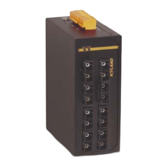
Structure and Interface 2 Structure and Interface Caution: It is recommended to purchase the port dustproof shield (optional) to keep ports clean and ensure switch performance. 2.1 Front Panel Figure 1 Front Panel of KIEN1008BA-6S/M-2T... - Page 9 Structure and Interface Figure 2 KIEN1008BA-EM-6S/M-2T (bare board) Table 2 Description...
-
Page 10: Top Panel
Structure and Interface 2.2 Top Panel PWR1 PWR2 +/L -/N -/N +/L Figure 3 Top Panel Table 3 Description of the Top Panel No. Identifier Description PWR1 PWR2 Power terminal block +/L -/N -/N +/L Grounding screw... -
Page 11: Mounting
Mounting 3 Mounting 3.1 Dimension Drawing 53.6 106.5 53.6 Figure 4 Dimensions for DIN-Rail Mounting (unit: mm) 53.6 106.5 53.6 Figure 5 Dimensions for Panel Mounting (unit: mm) - Page 12 Mounting Figure 6 Dimensions of Bare Board (unit: mm) Caution: As part of the heat dissipation system, the switch housing becomes hot during operation. Please use caution when coming in contact and avoid covering the switch housing when the switch is running. The figures in this manual are only for reference.
-
Page 13: Mounting Modes And Steps
Mounting 3.2 Mounting Modes and Steps The integrated device models support DIN-rail and panel mounting while bare board models can be embedded in other devices for integration. Before installation, make sure that the following requirements are met. 1) Environment:temperature (-40 to 85 ), ambient relative humidity (5% to 95%, non-condensing) 2) Power requirement:The power input is within the voltage range of... - Page 14 Mounting Dismounting Step 1: Insert the head of a screwdriver into the opening of the spring locking piece at the bottom from the left. Lift the handle of the screwdriver to open the spring locking piece of the connecting seat, as shown on the left of the following figure. Step 2: Move the device in direction 2 until the bottom of the device is detached from the DIN rail.
-
Page 15: Panel Mounting
Mounting 3.2.2 Panel Mounting Note: Purchase the plate (optional) for panel mounting. Panel Mounting Step 1: Use screws to secure the plate for panel mounting to the rear panel of the device. Step 2: Select the mounting position (on a wall or inner wall of a cabinet) for the device and guarantee adequate space and heat dissipation (dimensions: 53.6mm×135mm×106.5mm). - Page 16 Mounting Panel Dismounting Step 1: Loosen the four screws with a screwdriver. Pull the device upward until the four screws are in the Ф6.5 positions in the following figure. Then remove the plate for panel mounting from the four screws to detach the device from the wall or inner wall of the cabinet.
-
Page 17: Connection
Connection 4 Connection 4.1 10/100Base-T(X) Ethernet Port 10/100Base-T(X) Ethernet port is equipped with RJ45 connector. The port is self-adaptive. It can automatically configure itself to work in 10M or 100M state, full or half duplex mode. The port can also adapt to MDI or MDI-X connection automatically. - Page 18 Connection Wiring Sequence RJ45 connector RJ45 connector Straight-through cable Wiring sequence Cross-over cable Wiring sequence Figure 12 Connection Using Straight-through/Cross-over Cable Note: The color of the cable for RJ45 connector meets the 568B standard:1-orange and white, 2-orange, 3-green and white, 4-blue, 5-blue and white, 6-green, 7-brown and white, and 8-brown.
-
Page 19: 100Base-Fx Ethernet Port
Connection 4.2 100Base-FX Ethernet Port 100Base-FX Ethernet port is equipped with FC/ST/SC connector, and each port consists of TX (transmit) port and RX (receive) port. To enable data transmission between Device A and Device B, connect the TX port of Device A to the RX port of Device B, and the RX port of Device A to the TX port of Device B. -
Page 20: Grounding
Connection 4.3 Grounding Grounding protects the switch from lightning and interference. There- fore, you must ground the switch properly. You need to ground the switch before it is powered on and disconnect the grounding cable after the switch is powered off. The switch provides a grounding screw on the top panel for chassis grounding. -
Page 21: Power Terminal Block
Connection 4.4 Power Terminal Block You need to connect the power wires to the terminal block to provide power to the device. The device supports single (PWR1) and redun- dant (PWR1 and PWR2) power supply with a 5-pin 5.08mm-spacing plug-in terminal block. When the redundant power supply is used and one power input is faulty, the device can continue operating properly, thereby improving network reliability. - Page 22 Connection The following table lists the pin definitions of the 5-pin 5.08mm- spacing plug-in terminal block. Table 5 Pin Definitions of 5-Pin 5.08mm-Spacing Plug-in Terminal Block Wiring and Mounting Step 1: Ground the device properly according to section 4.3. Step 2: Remove the power terminal block from the device. Step 3: Insert the power wires into the power terminal block according to Table 5and secure the wires.
- Page 23 Connection PGND PWR2:-/N PWR1:-/N PWR2:+/L PWR1:+/L Plug Socket Figure 16 Connection of 5-Pin 5.08mm-Spacing Plug-in Terminal Block Caution: The switch supports 3.3DCW, 12DC and 24DCW power input (as listed in Table 1). Before connecting the device to power supply, make sure that the power input meets the power requirement.
-
Page 24: Leds
LEDs 5 LEDs Table 6 Front Panel LEDs Connection status (green) Speed (yellow) -
Page 25: Basic Features And Specifications
Basic Features and Specifications 6 Basic Features and Specifications... - Page 28 FAX: +86-10-88796678 Website: http://www.kyland.com Email: support@kyland.com For more information about KYLAND products, please visit our website: http://www.kyland.com...
Need help?
Do you have a question about the KIEN1008BA Series and is the answer not in the manual?
Questions and answers