
Related Manuals for KYLAND Ruby3A


Summary of Contents for KYLAND Ruby3A
- Page 1 Ruby3A Industrial Ethernet Switch Hardware Installation Manual Publication Data: Oct. 2017 Version: V1.0 No.:112023101...
- Page 2 All rights reserved. No part of this documentation may be excerpted, reproduced, translated, annotated or duplicated, in any form or by any means without the prior written permission of KYLAND Corporation. Copyright © 2017 Kyland Technology Co., Ltd.
- Page 3 Before using the device, read this manual carefully for personal and equipment safety. Please keep the manual for further reference. Kyland is not liable to any personal or equipment damage caused by violation of this notice.
- Page 4 Dispose of the device in accordance with relevant national provisions, preventing environmental pollution. In the following cases, please immediately shut down your power supply and contact your Kyland representative: Water gets into the equipment. Equipment damage or shell damage.
-
Page 5: Table Of Contents
Contents 1 Product Overview .......................1 2 Structure and Interface .......................2 2.1 Front Panel ........................2 2.2 Top Panel ........................3 3 Mounting ..........................5 3.1 Dimension Drawing ......................5 3.2 Mounting Modes and Steps ..................6 3.2.1 DIN-Rail Mounting ....................6 3.2.2 Panel Mounting ......................8 4 Connection ........................11 4.1 10/100/1000Base-T(X) Ethernet Port ................. -
Page 6: Product Overview
With PRP and HSR, the data is replicated and transmitted for seamless recovery when a link failure occurs, so that no packet loss occurs, and network transmission reliability is improved. Ruby3A supports DIN rail mounting and panel mounting. For details, see the following table. Table 1 Models Ruby3A-3G-L2-L2... -
Page 7: Structure And Interface
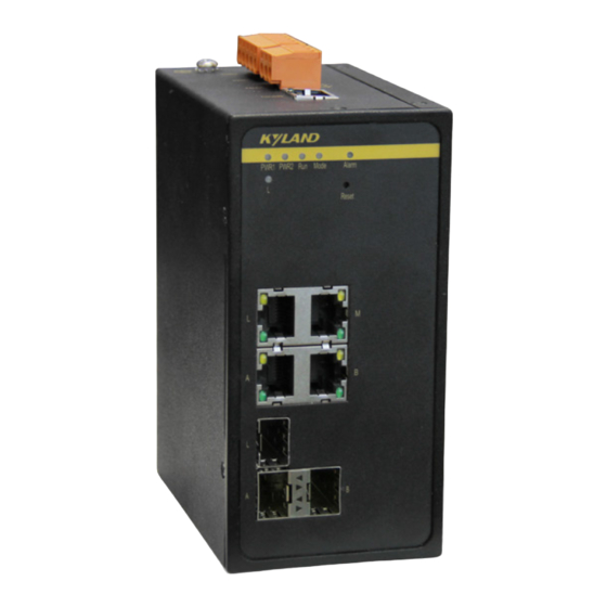
Structure and Interface 2 Structure and Interface Caution: It is recommended to purchase the port dustproof shield (optional) to keep ports clean and ensure device performance. 2.1 Front Panel Figure 1 Front Panel (1) Power 1 LED (2) Power 2 LED (3) Running LED (4) Operation mode LED (5) Alarm LED... -
Page 8: Top Panel
Structure and Interface 2.2 Top Panel Ruby3A-3G-L2-L2 Top Panel Figure 2 Ruby3A-3G-L2-L2 Top Panel Ruby3A-3G-HV Top Panel... - Page 9 Structure and Interface Figure 3 Ruby3A-3G-HV Top Panel...
-
Page 10: Mounting
Mounting 3 Mounting 3.1 Dimension Drawing Figure 4 Dimensions for DIN-Rail Mounting (unit: mm) Figure 5 Dimensions for DIN-Rail Mounting (unit: mm) Caution: As part of the heat dissipation system, the switch housing becomes hot during operation. Please use caution when coming in contact and avoid covering the switch housing when the... -
Page 11: Mounting Modes And Steps
Mounting switch is running. The figures in this manual are only for reference. 3.2 Mounting Modes and Steps The device supports both DIN-rail mounting and panel mounting. Before installation, make sure that the following requirements are met. 1) Environment: temperature (-40℃ to 85℃), ambient relative humidity (5% to 95%, non-condensing) 2) Power requirement: The power input is within the voltage range of the switch. - Page 12 Mounting Figure 6 DIN-Rail 1 Mounting DIN-Rail 1 Dismounting Step 1: As shown in the following figure, press the device downward and move the device in direction 1 until the bottom of the device is detached from the DIN rail. Step 2: Pull the device upward and move the device in direction 2 until the device is removed from the DIN rail completely.
-
Page 13: Panel Mounting
Mounting Figure 8 DIN-Rail 2 Mounting DIN-Rail 2 Dismounting Step 1: Insert the head of a screwdriver into the opening of the spring locking piece at the bottom from the left. Lift the handle of the screwdriver to open the spring locking piece of the connecting seat, as shown on the left of the following figure. - Page 14 Mounting Mounting Step 1: Use screws to fix the plate for panel mounting to the rear panel of the device. Step 2: Select the mounting position (on a wall or inner wall of a cabinet) for the device and guarantee adequate space and heat dissipation for it.
- Page 15 Mounting Figure 11 Panel Dismounting Caution: Cut off the power and disconnect all cables before mounting, dismounting or moving the equipment.
-
Page 16: Connection
Connection 4 Connection 4.1 10/100/1000Base-T(X) Ethernet Port 10/100/1000Base-T(X) Ethernet port is equipped with RJ45 connector. The port is self-adaptive. It can automatically configure itself to work in 10M, 100M, or 1000M state, full or half duplex mode. The port can also adapt to MDI or MDI-X connection automatically. You can connect the port to a terminal or network device with a straight-through or cross-over cable. -
Page 17: 1000Lx/Sx 10/100/1000Base-T(X) Sfp Slot
Connection Wiring Sequence Figure 13 Connection Using Straight-through/Cross-over Cable Note: The color of the cable for RJ45 connector meets the 568B standard: 1-orange and white, 2-orange, 3-green and white, 4-blue, 5-blue and white, 6-green, 7-brown and white, and 8-brown. 4.2 1000LX/SX 10/100/1000Base-T(X) SFP slot 1000LX/SX 10/100/1000Base-T(X) SFP slot (gigabit SFP slot) requires an SFP... -
Page 18: Sfp Optical Module
Connection IFSFP-S-LH-LC-1310-40 100Base-X port 1310nm 40km IGSFP-10/100/1000BASE- 10/100/1000Base- RJ45 T-RJ45 T(X) port Note: The device uses the SFP module that supports digital diagnosis to support the optical power detection function of the SFP slot. For details about the SFP module, consult our sales or technical support personnel. -
Page 19: Sfp Electrical Module
Connection Figure 16 Connecting the SFP Optical Module Identify the RX port and TX port of an SFP optical module: 1. Insert the two connectors in one end of two fibers into the SFP module, and those in the other end into the peer module. 2. -
Page 20: 1000Lx/Sx 10/100/1000Base-T(X) Combo Port
Connection Figure 18 Connecting the SFP Electrical Module 4.3 1000LX/SX 10/100/1000Base-T(X) Combo Port As shown in following table, the 1000LX/SX, 10/100/1000Base-T(X)Combo port consists of one 1000Base-X port(GX) and one 10/100/1000Base-T(X) Ethernet port, and only one of the two ports can be used at one time, and the 1000Base-X port has priority over 10/100/1000Base-T(X) port. -
Page 21: Grounding
Connection Figure 19 Console Port DB9-RJ45 Console Cable One end of a DB9-RJ45 console cable is the DB9 connector to be inserted into the 9-pin serial port of a PC, and the other end is crimped RJ45 connector to be inserted into the console port of the switch. -
Page 22: Power Terminal Block
There is a power terminal block on the top panel of the device. You need to connect the power wires to the terminal block to provide power to the device. The Ruby3A-3G-L2-L2 device supports redundant power input with a 5-pin 5.08mm-spacing plug-in terminal block. - Page 23 Connection PGND PGND PWR2: - PWR2: N PWR2: + PWR2: L Wiring and Mounting Step 1: Ground the device properly according to section 4.5. Step 2: Remove the power terminal block from the device. Step 3: Insert the power wires into the power terminal block according to Table 6 and secure the wires.
-
Page 24: Alarm Terminal Block
Connection PWR:- PWR:N PWR:+ PWR:L Wiring and Mounting Step 1: Ground the device properly according to section 4.5. Step 2: Remove the power terminal block from the device. Step 3: Insert the power wires into the power terminal block according to Table 8 and secure the wires. - Page 25 Connection 5.08mm-spacing plug-in terminal block. Figure 23 Alarm Terminal Block (socket) Electrical parameters of the relay: Max Switch Voltage: 250VAC/220VDC; Max Switch Current: 2A Max Switching Power: 60W Dielectric Strength: 2KV Note: Pin 1 and pin 2 are normally-open contacts; pin 2 and pin 3 are normally-closed contacts. When the switch works properly, pin 1 and pin 2 are closed, pin 2 and pin 3 are open;...
-
Page 26: Reset
Reset 5 Reset The device provides a Reset button on the front panel. The button can be used to restart the device or restore factory default settings. You can restart the device by pressing and holding the button for 0.5 to 3 second. -
Page 27: Leds
LEDs 6 LEDs Table 11 Front Panel LEDs State Description Power 1 is connected and operates properly. Power 1 LED Power 1 is not connected or operates abnormally. Power 2 is connected and operates properly. Power 2 LED Power 2 is not connected or operates abnormally. Blinking The CPU operates properly. -
Page 28: Switch Access
Switch Access LED 1 and LED 2 indicate the status of the left gigabit SFP slot, while LED 3 and LED 4 indicate the status of the right gigabit SFP slot. 1000M working state (1000Base-TX) 1000LX/SX SFP Optical Module 10/100/1000Base-T 10/100M working state or no connection (X) SFP slot speed 1000M working state (1000Base-TX) - Page 29 Switch Access Figure 24 Creating a Connection Step 4: Connect the communication port in use, as shown in the following figure. Figure 25 Selecting a Serial Port Note: To confirm the communication port in use, right-click [My Computer] and select [Property]. Click [Hardware] →...
-
Page 30: Access Through Telnet
Switch Access Figure 26 Setting Port Parameters Step 6: Click OK to enter the switch CLI. Then the following commands can be used to perform operations. Table 12 CLI Commands View Command Description General mode SWITCH>enable Enter the privileged mode. Privileged mode SWITCH#show interface vlan 1 Query the default IP address of the switch. -
Page 31: Access Through Web
Step 2: Enter the IP address of the device in the address box of the browser. The user login interface is displayed. You can log in to the Web UI by default user name "admin" and password "kyland". Note: Firefox browser is recommended. -
Page 32: Basic Features And Specifications
Maximum Voltage Power Identifier Rated Voltage Range Range HV(220AC/DCW) 100-240VAC,50/60Hz;110-220VDC 85-264VAC/77-300VDC L2(24DCW) 24-48VDC 18-72VDC Ruby3A-3G-L2-L2 : 5-pin 5.08mm-spacing plug-in terminal Terminal block block Ruby3A-3G-HV:3-pin 7.62mm-spacing plug-in terminal block Rated Power Consumption Rated power consumption 6.5W (MAX) Physical Characteristics Housing Metal, fanless... - Page 33 Basic Features and Specifications Warranty five years...
- Page 34 FAX: +86-10-88796678 Website: http://www.kyland.com Email: support@kyland.com For more information about KYLAND products, please visit our website: http://www.kyland.com...
Need help?
Do you have a question about the Ruby3A and is the answer not in the manual?
Questions and answers