
Related Manuals for KYLAND Aquam5S Series


Summary of Contents for KYLAND Aquam5S Series
- Page 1 Aquam5S/Aquam8S/Aquam9S Series Industrial Ethernet Switches Hardware Installation Manual Publication Date: Jul. 2021 Version: V1.3 No.: 112023082...
- Page 2 Aquam5S/Aquam8S/Aquam9S Series Industrial Ethernet Switches Hardware Installation Manual Disclaimer: Kyland Technology Co., Ltd. tries to keep the content of this manual as accurate and as updated as possible. This document is not guaranteed to be error-free, and we reserve the right to amend it without notice to users.
- Page 3 Before using the device, read this manual carefully for personal and equipment safety. Please keep the manual for further reference. Kyland is not liable to any personal or equipment damage caused by violation of this notice.
- Page 4 Dispose of the device in accordance with relevant national provisions, preventing environmental pollution. In the following cases, please immediately shut down your power supply and contact your Kyland representative: Water gets into the equipment. Equipment damage or shell damage.
-
Page 5: Table Of Contents
Contents 1 Product Overview ......................1 2 Structure and Interface ..................... 2 3 Mounting ........................... 5 3.1 Dimension Drawing ....................5 3.2 Mounting Modes and Steps ..................5 4 Connection ........................8 4.1 10/100Base-T(X) Ethernet Port .................. 8 4.1.1 Functions ......................8 4.1.2 Pin Definitions and Wiring Sequence .............. -
Page 6: Product Overview
1 Product Overview Aquam5S/Aquam8S/Aquam9S includes a series of high-performance industrial Ethernet switches developed by Kyland. The series devices are applicable to the industrial field of various harsh environment with strict requirements on reliability due to the solid closed housing, fanless but heat dissipation-capable single-rib shaped chassis, overcurrent, overvoltage for power input, sound EMC protection of M12 ports, and IP65 protection class. -
Page 7: Structure And Interface
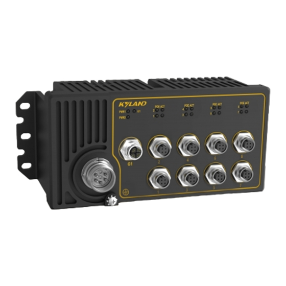
Structure and Interface 2 Structure and Interface Caution: It is recommended to purchase the port dustproof shield (optional) to keep ports clean and ensure switch performance. If the equipment is used in a manner not specified by the manufacturer, the protection provided by the equipment may be impaired. - Page 8 Structure and Interface Aquam9S Front Panel Figure 1 Front Panel (1) Power 1 LED (2) Power 2 LED (3) 10/100Base-T(X) Ethernet Port POE LED (4) 10/100Base-T(X) Ethernet port connection status LED (5) 10/100Base-T(X) POE Ethernet port...
- Page 9 Structure and Interface (6) Grounding screw (7) Power port (8) 10/100/1000Base-T(X) Ethernet port (9) 10/100/1000Base-T(X) Ethernet port connection status LED...
-
Page 10: Mounting
Mounting 3 Mounting 3.1 Dimension Drawing Figure 2 Dimensions (unit: mm) Caution: As part of the heat dissipation system, the switch housing becomes hot during operation. Please use caution when coming in contact and avoid covering the switch housing when the switch is running. - Page 11 Mounting met. 1) Environment: temperature (-40℃ to 70℃), ambient relative humidity (5% to 95%, non-condensing). 2) Power requirement: The power input is within the voltage range of the switch. 3) Grounding resistance: <5 4) No direct sunlight, distant from heat source and areas with strong electromagnetic interference.
- Page 12 Mounting Dismounting Loosen the screws with a screwdriver, remove the screws and device from the wall or inner wall of a cabinet to complete dismounting. Caution: Cut off the power and disconnect all cables before mounting, dismounting or moving the equipment.
-
Page 13: Connection
Connection 4 Connection 4.1 10/100Base-T(X) Ethernet Port 4.1.1 Functions Data Transmission 10/100Base-T(X) Ethernet port is equipped with M12 connector, which is dustproof, waterproof, and anti-vibration. The port is self-adaptive. It can automatically configure itself to work in 10M or 100M state, full or half duplex mode. The port can also adapt to MDI or MDI-X connection automatically. - Page 14 Connection Figure 5 RJ45 Port You can use an M12-M12 or M12-RJ45 cable to connect the port for communication. The preceding figures show the pin numbers of an M12 port and an RJ45 port. For pin definitions, see the following table. Table 2 Pin Definitions of M12/RJ45 Port MDI-X Signal MDI Signal...
- Page 15 Connection Figure 6 Connection Using Straight-through/Cross-over Cable Note: The color of the cable for RJ45 connector meets the 568B standard: 1-orange and white, 2-orange, 3-green and white, 4-blue, 5-blue and white, 6-green, 7-brown and white, and 8-brown. The 1 and 3, 2 and 4 pins on the M12 interface are differentiated signal pins in pairs. The orange-and-white and orange pair, green-and-white and green pair, blue-and-white and blue pair, and brown-and-white and brown pair in twist pair cables must be used in correct pairs while being connected with the signal pins.
-
Page 16: 10/100/1000Base-T(X) Ethernet Port
Connection 4.2 10/100/1000Base-T(X) Ethernet Port 10/100/1000Base-T(X) Ethernet port is equipped with M12 connector, which is dustproof, waterproof, and anti-vibration. The port is self-adaptive. It can automatically configure itself to work in 10M or 100M state, full or half duplex mode. The port can also adapt to MDI or MDI-X connection automatically. - Page 17 Connection Transmit/Receive Data (TRD0-) Transmit/Receive Data (TRD1-) Transmit/Receive Data (TRD3+) Transmit/Receive Data (TRD2+) Transmit/Receive Data (TRD3-) Transmit/Receive Data (TRD2-) Transmit/Receive Data (TRD2+) Transmit/Receive Data (TRD3+) Transmit/Receive Data (TRD2-) Transmit/Receive Data (TRD3-) RJ45 Port Transmit/Receive Data (TRD1+) Transmit/Receive Data (TRD0+) Transmit/Receive Data (TRD1-) Transmit/Receive Data (TRD0-) Transmit/Receive Data (TRD0+) Transmit/Receive Data (TRD1+)
-
Page 18: Grounding
Connection Figure 9 Connection Using Straight-through/Cross-over Cable Note: The color of the cable for RJ45 connector meets the 568B standard: 1-orange and white, 2-orange, 3-green and white, 4-blue, 5-blue and white, 6-green, 7-brown and white, and 8-brown. 4.3 Grounding Grounding protects the device from lightning and interference. Therefore, you must ground the device properly. -
Page 19: Power Port
Connection to the grounding screw and firmly connect the other end to ground. Note: . Cross-sectional area of the chassis grounding cable>2.5mm ; Grounding resistance<5 Earth line should be less than 3m. 4.4 Power port There is a power port on the front panel of the device. You need to connect the power cable to the power port to provide power to the device. - Page 20 Connection Wiring and Mounting Step 1: Ground the device properly according to section 4.2. Step 2: Insert one end of the power cable into the M23 connector firmly. Step 3: Insert the M23 connector with the connected cable into the power port on the device. Step 4: Connect the other end of the power cable to an external power supply system according to the power supply requirements of the device.
-
Page 21: Leds
LEDs 5 LEDs Table 5 Front Panel LEDs State Description The power 1 is connected and operates properly. Power 1 LED-PWR1 The power 1 is not connected or operates abnormally. The power 2 is connected and operates properly. Power 2 LED-PWR2 The power 2 is not connected or operates abnormally. -
Page 22: Basic Features And Specifications
Basic Features and Specifications 6 Basic Features and Specifications Power Requirements Power Identifier Rated Voltage Range Maximum Voltage Range 24-110VDC 16.8-154VDC Terminal Block 5-pin M23 connector Rated Power Consumption Rated Power Without PD: 0.4A @24VDC (MAX) Consumption With 80W PD: 7.0A@24VDC (MAX) Physical Characteristics Housing Metal, fanless... - Page 23 Basic Features and Specifications Warranty Warranty Five years...
Need help?
Do you have a question about the Aquam5S Series and is the answer not in the manual?
Questions and answers