Sign In
Upload
Download
Table of Contents
Contents
Add to my manuals
Delete from my manuals
Share
URL of this page:
HTML Link:
Bookmark this page
Add
Manual will be automatically added to "My Manuals"
Print this page
×
Bookmark added
×
Added to my manuals
Manuals
Brands
Eneo Manuals
Security Camera
MEB-55M2812M0A
User manual
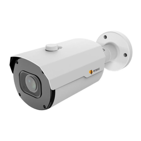
Eneo MEB-55M2812M0A User Manual
1/2.8" hd camera / hd dome, day&night, 2592x1944, infrared 2,7-13,5mm, 12vdc, ip67
Hide thumbs
1
2
3
4
Table Of Contents
5
6
7
8
9
10
11
12
13
14
15
16
page
of
16
Go
/
16
Contents
Table of Contents
Bookmarks
Table of Contents
Table of Contents
Introduction
Features
Camera Overview
Installation and Configuration
Package Contents
Installation
VF Bullet Camera
VF Turret Camera
Fixed Turret Camera
Connections
OSD Menu Description
OSD Menu Structure
OSD Menu Operation
Appendix
Specification
Advertisement
Quick Links
1
Installation and Configuration
Download this manual
EN
User Manual
1/2.8" HD Camera / HD Dome,
Day&Night, 2592x1944, Infrared
2,7-13,5mm, 12VDC, IP67
MEB-55M2812M0A
MED-65M2812M0A
Table of
Contents
Previous
Page
Next
Page
1
2
3
4
5
Advertisement
Table of Contents
Need help?
Do you have a question about the MEB-55M2812M0A and is the answer not in the manual?
Ask a question
Questions and answers
Related Manuals for Eneo MEB-55M2812M0A
Security Camera Eneo MEB-62V2812M0A User Manual
1/2.9"hd camera, multisignal,day&night, 1920x1080, infrared, 12vdc, ip66 (40 pages)
Security Camera Eneo MED-62V2812M0A User Manual
1/2.8 inch hd dome, fixed, day&night, 1920x1080, 12vdc, 2.8-12mm, infrared, ip66 (32 pages)
Security Camera Eneo MEB-62F0036P0A User Manual
(32 pages)
Security Camera Eneo MEB-62V2812P0B Quick Installation Manual
(52 pages)
Security Camera Eneo MEP-63M2812M0A User Manual
1/2.9 inch hd dome, fixed, day&night, 1920x1080, 2.8- 12mm, infrared, 12vdc, ip66 (21 pages)
Security Camera Eneo MEB-65M2713M0A User Manual
1/2.7" hd camera / dome, day&night, 2592x1944, infrared, ip66 (17 pages)
Security Camera Eneo MEM-44F0025M0A User Manual
1/2.8" hd camera, day&night, 2592x1944, 2.5mm, 12vdc (25 pages)
Security Camera Eneo MEB-62V2713P0A Quick Installation Manual
1/2.8” hd camera, day&night, 1920x1080, infrared, 2.7 - 13,5 mm, 12vdc, ip66 (28 pages)
Security Camera Eneo MED-62V2713M0A Quick Installation Manual
1/2.8” hd dome, fixed, day&night, 1920x1080, 12vdc, 2.7-13.5 mm, infrared, ip66 (28 pages)
Security Camera Eneo MED-62V2713M0A User Manual
1/2.8” hd dome, fixed, day&night, 1920x1080, 12vdc,2.7-13.5 mm, infrared, ip66 (32 pages)
Security Camera Eneo MEC-52C0000M0A User Manual
1/2.8” hd camera, day&night, 1920x1080, d-wdr, c/cs, 12vdc (32 pages)
Security Camera Eneo MED-62V2812M0B User Manual
(32 pages)
Security Camera Eneo 219547 Quick Installation Manual
(52 pages)
Security Camera Eneo MEP-62M2812M0A User Manual
(21 pages)
Security Camera Eneo MEP-62M2812M0A Quick Installation Manual
(36 pages)
Security Camera Eneo MED-65M2812M0A User Manual
1/2.8" hd camera / hd dome, day&night, 2592x1944, infrared 2,7-13,5mm, 12vdc, ip67 (16 pages)
This manual is also suitable for:
Med-65m2812m0a
Table of Contents
Print
Rename the bookmark
Delete bookmark?
Delete from my manuals?
Login
Sign In
OR
Sign in with Facebook
Sign in with Google
Upload manual
Upload from disk
Upload from URL


Need help?
Do you have a question about the MEB-55M2812M0A and is the answer not in the manual?
Questions and answers