
Related Manuals for Eneo MEB-62V2713P0A


Summary of Contents for Eneo MEB-62V2713P0A
- Page 1 Quick Installation Guide 1/2.8” HD Camera, Day&Night, 1920x1080, Infrared, 2.7 - 13,5 mm, 12VDC, IP66 MEB-62V2713P0A...
-
Page 2: Table Of Contents
Table of contents Parts supplied .......................5 Part names ........................6 Installation instructions ....................7 Pan & Tilt adjustments ..............................7 Power supply connections .............................9 Operating instructions ....................10 Using OSD controller..............................10 Description of the joystick operation ....................... 10 Using Video Format Switch ............................10 DIP Switch setting .............................. - Page 3 Safety instructions General safety instructions • Before switching on and operating the system, first read this safety advice and the operating instructions. • Keep the operating instructions in a safe place for later use. • Installation, commissioning and maintenance of the system may only be carried out by authorised individuals and in accordance with the installation instructions - ensuring that all applicable standards and guidelines are followed.
- Page 4 Class A device note This is a Class A device. This device can cause malfunctions in the living area; in such an event, the operator may need to take appropriate measures to compensate for these. WEEE (Waste Electronical & Electronic Equipment) Correct Disposal of This Product (Applicable in the European Union and other European countries with separate collection systems).
-
Page 5: Parts Supplied
Parts supplied • Camera • Operating Instruction • Mounting Template • Plastic Anchor: 6 x 30 mm (3pcs) • Mounting Screw: 3.5 x 25 mm (3pcs) • L-Wrench (1pc) • Video Sub-out Cable (1pc) -
Page 6: Part Names
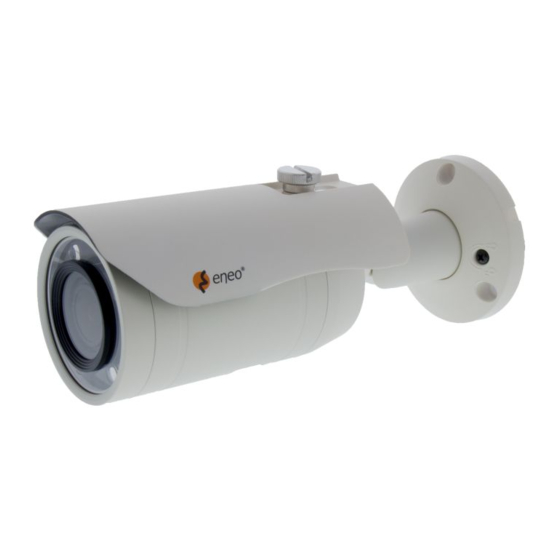
Part names Sunshield bolt Sunshield Power cable Dual window Bracket Rear case Front case Case open Focus lever Zoom lever Focus/Zoom Adjustment (Vari-focal lens type only) -
Page 7: Installation Instructions
Installation instructions CAUTION: The camera’s base should be attached to a structural object, such as concrete, hard wood, wall stud or ceiling rafter that supports the weight of the camera. If necessary use appro- priate mounting material (e.g. anchors) instead of the material enclosed with the camera. - Page 8 1. Pan limit: Pan is limited to +/- 90°. 2. Tilt limit: Tilt is limited to 0°(2°) min ~ 90° max. for wall(ceiling) installation respec- tively with reference to the wall(ceiling) when the inclination of camera module is 0°, that is, the image is aligned horizontally. on the wall on the ceiling 3.
-
Page 9: Power Supply Connections
Adjustment of viewing angle with 3-Axis bracket. Tilt 1. Lock/Unlock Screw Inclination 2. Sub-Lock Screw CAUTION: Extreme care should be taken NOT to scratch the surface of window while the camera installing or adjusting. Care should be taken the cable is NOT to be damaged, kinked or exposed in the hazardous area. -
Page 10: Operating Instructions
Operating instructions Using OSD controller Setup menu can be accessed and controlled by OSD control joy stick inside of the camera unit. Five commands are available with the joy Video Sub-out connector OSD Control & Video format Joystick Video format DIP Switch s t i c k . -
Page 11: Joystick Setting
Joystick setting Switching video format is available by Video format joystick. If you want to set the HD video format, set the DIP Switch to HD mode first. Then set the one of HD Video format by joystick. The default setting is TVI mode. 1. - Page 12 MENU SUB MENU CONFIGURATION SHUTTER FLK, 1/60(1/50), 1/30(1/25), AUTO, x30~x2, 1/50000~1/200 0~15 SENS UP OFF, AUTO (2x~30x) EXPOSURE BRIGHTNESS 1~100 D-WDR ON(LEVEL:0~8), AUTO, OFF DEFOG OFF, AUTO POS/SIZE, GRADATION(0~2), DEFAULT HSBLC SELECT AREA1~4 DISPLAY ON, OFF BLACK MASK ON, OFF BACKLIGHT LEVEL 0~100...
- Page 13 MENU SUB MENU CONFIGURATION CAM TITLE OFF, ON FREEZE OFF, ON D-EFFECT MIRROR MIRROR, V-FLIP, ROTATE, OFF NEG. IMAGE SELECT AREA1~4 DISPLAY OFF, ON(POSITION, SIZE) SENSITIVITY 0~100 MOTION COLOR Green, Red, White, Blue TRANS 0.00~1.00 ALARM* VIEW TYPE, OSD VIEW, ALARM OUT, TIME DEFAULT SELECT AREA1~4...
- Page 14 Inhaltsverzeichnis Lieferumfang .......................17 Bezeichnungen von Gerätekomponenten ...............18 Installationsanweisungen ..................19 Einstellung von Schwenkung und Neigung ......................19 Stromversorgungsanschlüsse ............................ 21 Betriebsanleitung .......................22 Bildschirmmenü-Steuerung verwenden ....................... 22 Beschreibung der Joystick-Bedienung ..................... 22 Verwendung des Videoformat-Schalters ....................... 23 DIP-Schalter-Einstellung ............................23 Joystick-Einstellung ..............................23 Bildschirmmenü...
- Page 15 Sicherheitsanweisungen Sicherheitshinweise allgemein • Bevor Sie das System anschließen und in Betrieb nehmen, lesen Sie zuerst diese Sicherheitshinweise und die Betriebsanleitung. • Bewahren Sie die Betriebsanleitung sorgfältig zur späteren Verwendung auf. • Montage, Inbetriebnahme und Wartung des Systems darf nur durch dafür autorisierte Personen vorgenom- men und entsprechend den Installationsanweisungen - unter Beachtung aller mitgeltenden Normen und Richtlinien - durchgeführt werden.
- Page 16 • Bei abgedunkelter Umgebung und direktem Blick in den IR-Scheinwerfer ist ein Sicherheitsabstand von > 1 m zum Scheinwerfer einzuhalten. • Unsichtbare LED Strahlung nicht direkt mit optischen Instrumenten (z.B. Lupe, Vergrößerungsglas oder Mikroskop) betrachten, da dies Augen gefährden kann, LED Klasse 1M. •...
-
Page 17: Lieferumfang
Lieferumfang • Kamera • Betriebsanleitung • Bohrschablone • • Befestigungsschraube: 3,5 x 25 mm (3 St.) • Inbusschlüssel (1x) • Video Sub-out Kabel (1 St.) -
Page 18: Bezeichnungen Von Gerätekomponenten
Bezeichnungen von Gerätekomponenten Bolzen für Sonnenschutzdach Sonnenschutzdach Netzkabel Doppelglasiges Fenster Kamerahalterung Hinteres Gehäuse Vorderes Gehäuse Geöffnetes Gehäuse Fokus-Hebel Zoom-Hebel Zoom- und Fokuseinstellung (nur das Modell mit variabler Brennweite) -
Page 19: Installationsanweisungen
Installationsanweisungen ACHTUNG: Die Kamerahalterung sollte an einem Bauelement wie etwa Beton, Hartholz, einem Wandständer oder Deckenbal- ken befestigt werden, welches das Gewicht der Kamera trägt. Verwenden Sie, falls erforderlich, geeignetes Befestigungsmateri- al (z.B. Dübel) anstelle des mitgelieferten Materials. 1. Halten Sie die Bohrschablone an die Installationsstelle und bohren Sie die Löcher in Decke oder Wand, falls erforderlich. - Page 20 1. Schwenkwinkel: Der Schwenkwinkel ist auf +/- 90° begrenzt. 2. Neigungswinkel: Die Neigung ist bei Wand- (bzw. Decken)-Installation auf min. 0°(2°) bis max. 90° begrenzt, wobei vorausgesetzt wird, dass die Neigung des Kameramoduls in Bezug auf die Wand (bzw. Decke) 0° ist, d.h., dass das Bild hori- zontal ausgerichtet ist.
-
Page 21: Stromversorgungsanschlüsse
Anpassung des Betrachtungswinkels mit einem 3-Achsen-Halterung Neigen Schwenken 1. Schraube zum Verriegeln/Entriegeln Neigung 2. Sicherungsschraube ACHTUNG: Achten Sie besonders darauf, die Fensteroberfläche der Kamera während der Installation oder der Einstellung NICHT zu verkratzen. Es muss sorgfältig darauf geachtet werden, das Kabel NICHT zu beschädigen, zu knicken oder Gefahrenbereichen auszusetzen. -
Page 22: Betriebsanleitung
Betriebsanleitung Bildschirmmenü-Steuerung verwenden Zugriff und Steuerung des Konfigurationsmenüs können über den Joystick zur Bild- schirmmenü-Steuerung im Inneren des Kameragehäuses erfolgen. Fünf Befehle stehen mit dem Joystick zur Verfügung. Video Sub-out Anschluss OSD-Steuerung & Videoformat-Joystick Videoformat-DIP-Schalter Beschreibung der Joystick-Bedienung 1. SET-Taste (●): Zum Zugreifen auf das Menü oder Eingeben der Einstellung. Um in das Hauptmenü... -
Page 23: Verwendung Des Videoformat-Schalters
Verwendung des Videoformat-Schalters DIP-Schalter-Einstellung Die Einstellung des DIP-Schalters hat Vorrang. Wenn der Schalter auf CVBS eingestellt ist, ist nur der CVBS-Ausgang sowohl für den Hauptvideo-Ausgang als auch für den Sub-Out- Ausgang verfügbar. Bitte beachten Sie, dass die Kamera nur ein Video sowohl für den Hauptvideo-Ausgang als auch für den Sub-Out-Ausgang erzeugt. -
Page 24: Bildschirmmenü-Übersicht
Bildschirmmenü-Übersicht MENÜ SUB MENU CONFIGURATION MODUS INDOOR, OUTDOOR (Innenräume, Außenbereiche) IRIS SPEED (Geschwin- Objektiv digkeit der Blende) MANUAL (MANUELL) DN DWELL (Tag/ FOCUS ASSIST Nacht Verweilzeit) SHUTTER FLK, 1/60(1/50), 1/30(1/25), AUTO, x30~x2, 1/50000~1/200 (Verschluss) 0~15 SENS UP OFF, AUTO (2x~30x) EXPOSURE BRIGHTNESS 1~100... - Page 25 MENÜ SUB MENU CONFIGURATION AUTO D->N(AGC/CDS), D->N(DELAY), N->D(AGC/CDS), N->D(DELAY) D->N(DELAY), N->D(DELAY) TAG/NACHT BURST, IR SMART, IR PWN* COLOR (Farbe) 2D-DNR LOW, MIDDLE, HIGH 3DNR (AHD only LOW, MIDDLE, HIGH (nur AHD)) CAM TITLE OFF (AUS), ON (EIN) (KAMERATITEL) FREEZE OFF (AUS), ON (EIN) D-EFFECT (Digitale MIRROR (Spiegeln) (SPIEGELN / VERTIKAL SPIEGELN / DREHEN / AUS)
-
Page 26: Further Information
• the product detail pages on the eneo website (www.eneo-security.com), • the eneo download portal (https://datacloud.videor.com/s/eneodownloadpor- tal). In case that previous link is broken, the latest link to the eneo download portal can be found on the respective eneo product page at www.eneo-security.com. - Page 28 VIDEOR E. Hartig GmbH Exclusive distribution through specialised trade channels only. VIDEOR E. Hartig GmbH Carl-Zeiss-Straße 8 63322 Rödermark/Germany Tel. +49 (0) 6074 / 888-0 Technical changes reserved Fax +49 (0) 6074 / 888-100 www.videor.com...
Need help?
Do you have a question about the MEB-62V2713P0A and is the answer not in the manual?
Questions and answers