Table of Contents
Advertisement
Quick Links
Advertisement
Table of Contents

Subscribe to Our Youtube Channel
Related Manuals for Inficon LDM250


Summary of Contents for Inficon LDM250
- Page 1 Operating Manual LDM250/LDM450/LDM650 Low Voltage Multipoint unit English ·...
- Page 2 INFICON LDM 250 450 650 Low voltage Multipoint unit ..................... 3 English ................................... 9 (WD) 724-250 450 650 -Low Voltage Operating Manual 220627.docx 2/15...
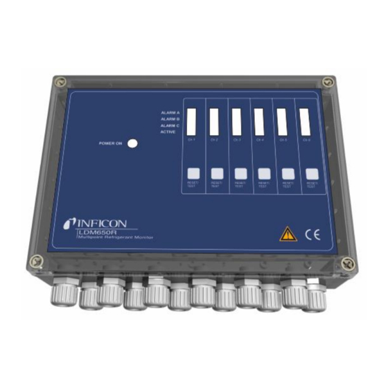
- Page 3 INFICON LDM 250 450 650 Low voltage Multipoint unit Fig. 1 3/15 (WD) 724-250 450 650 -Low Voltage Operating Manual 220627.docx...
- Page 4 INFICON Wiring diagram (WD) 724-250 450 650 -Low Voltage Operating Manual 220627.docx 4/15...
- Page 5 INFICON Logical matrix T<Xmin, X = delay in minutes. Letter U = signal from sensor (Vdc). LEDs (terminal board) Power Buzzer (disabled via jumper) no indication LEDs (per channel) Power/active Flash Flash Alarm C (low level) (Vdc) Flash Flash Flash...
- Page 6 INFICON (WD) 724-250 450 650 -Low Voltage Operating Manual 220627.docx 6/15...
- Page 7 INFICON 7/15 (WD) 724-250 450 650 -Low Voltage Operating Manual 220627.docx...
- Page 8 INFICON (WD) 724-250 450 650 -Low Voltage Operating Manual 220627.docx 8/15...
-
Page 9: Table Of Contents
INFICON English LDM 250/450/650 Low voltage Operating Manual 1. Table of Contents Features ..............................10 Models ..............................11 Function ..............................11 4.1 AUTO/MANUAL ALARM RESET ......................11 4.2 ALARM TIME DELAY (T1) ........................11 RESET/TEST/SERVICE-BUTTON (7) ..................11 4.3.1 SERVICE MODE ..........................12 4.3.2... -
Page 10: Features
- Low voltage output for auxiliary alarm indication. Please Note! The LDM250, LDM450 and LDM650 are normally supplied with default set alarm thresholds. These must be verified or reset during commissioning. Alarm levels must always be set on each channel for proper gas and detector type. -
Page 11: Models
INFICON 3. Models (sensors included) Model Used for 724-250-G1 two channels(sensors) 724-450-G1 four channels(sensors) 724-650-G1 six channels(sensors) 4. Function After connecting each detector and applying power, the green LED on each channel will flash as the pre-heat process commences. After approximately 4 minutes the green LED will illuminate permanently, and the sensor is fully operational. -
Page 12: Service Mode
INFICON 4.3.1 SERVICE MODE Pressing the” Reset/Test/Service” button (7) for 10 seconds will inhibit all alarm functions for the chosen channel for 60 minutes. Service mode is indicated by all LEDs on the chosen channel is flashing. A new 60 minute inhibit period can be initiated by repeating the process. Normal operation will be automatically resumed after 60 minutes or can be cancelled by pressing the “Reset/Test/ Service”-button briefly. -
Page 13: Remote Sensors
LDMR series is a range of remote sensors designed for use with the LDM units. Low voltage LDM250, LDM450, or LDM650 units include either 2, 4, or 6 LDMR remote sensors for detecting HFCs, HCFCs, and mixtures and carbon dioxide (CO2). - Page 14 INFICON Standard Housing: ABS/PC plastic, (IP67) Power supply: 24 AC/ 24V DC, max 10VA Status Indication: Common Power LED Individual LED channel indication of sensor active and 3 alarm levels. Inputs: 2, 4 or 6 channels 0-5VDC Alarm levels: 3 levels/channel, individually set within 0,5...4,8V...
- Page 15 Due to our continuing program of product improvements, specifications are subject to ch ange without notice. All trademarks are the property of their respective owners. TEK-Check and Wey-TEK are trademarks of INFICON. All other trademarks are the property of their res ©2022 INFICON...
Need help?
Do you have a question about the LDM250 and is the answer not in the manual?
Questions and answers