
Related Manuals for CardioQuip MCH-1000

Summary of Contents for CardioQuip MCH-1000
- Page 1 Model MCH-1000 Operator/Service Manual Cardiopulmonary Bypass Temperature Controller Publication date: June 15, 2022 LBL-01 V5 P/N 1000-05-1178...
- Page 2 Date Change Approval 4/8/09 Original version 5/4/10 Added disposal procedures for standards compliance 3/21/12 Updated to R2, added MCH-1000(m) information 3/27/14 Added Cardioplegia Shared Channel (CSC) Module information 8/1/14 Updated maintenance procedures 11/4/14 Added Thermo-Electric Cooling (TEC) Module information 6/15/15...
- Page 3 CardioQuip is prohibited. Manufacturer’s Responsibility CardioQuip may consider itself responsible for any effect on the safety, reliability and performance of the equipment if and only if: •...
-
Page 4: Table Of Contents
Obtaining Service ................................. Service Contact Information ............................Limited Warranty ................................Storage .................................... Transportation ................................Lifting ....................................Overview ..............................MCH-1000(i) Hardware Overview ..........................MCH-1000(m) Hardware Overview .......................... Operation Overview ..............................Add Ice! ................................... Control Screens ............................Power-on ..................................Water Level .................................. - Page 5 ................................Airflow Redirection Hood Installation ............................ MCH Operation ............................Unpacking ..................................Physical Inspection ............................... Initial Operation Check ..............................MCH-1000(i) Control Module Check ............................Basic Function Test ..................................Temperature Control System Test ............................Alarm Tests ....................................Terminating Operation ................................Current Test ....................................
-
Page 6: General Information
GENERAL INFORMATION Introduction The CardioQuip Modular Cooler-Heater (MCH) brings easy and accurate temperature control to the operating room. The latest touchscreen technology offers fast, user-friendly, multi- language device control. Redundant software and hardware failsafes ensure patient safety. A combination of audible and visual alerts enable effective monitoring without undue distraction. -
Page 7: Warnings And Precautions
Contact CardioQuip Customer Service for details regarding servicing assistance. WARNING: If the external tubing appears cloudy or discolored, immediately remove the device from service and contact CardioQuip Customer Service for details regarding servicing assistance. WARNING: Do NOT move modules or accessories between cooler-heater devices to prevent possible cross-contamination. - Page 8 WARNING: Servicing of this unit shall be performed by authorized CardioQuip technicians only. Improper repair can result in patient injury and/or damage to the system. WARNING: This device must not be connected to a heat exchanger or blanket with a manufacturer recommended maximum pressure rating of less than 83 kPa (<12 psi).
- Page 9 CAUTION: Do not use sharp objects to adjust or select switches on the control panel. CAUTION: Do not lift the MCH by the drain or water/hose connections. Lifting by these connectors will cause equipment damage. GENERAL INFORMATION | Warnings and Precautions...
-
Page 10: Device Labeling
Pour indiquer la représentation d'une limite inférieure de la To signify a minimum temperature limit. in ISO 3864. des bornes du connecteur, etc. Note - La signification de ce symbole graphique dépend de etc. Note - The meaning of this graphical symbol depends upon température, ou la mise en service (ou l'arret) de Safety 36 Note 1 - Pour marquer la fonction contrôle des piles,... -
Page 11: Specifications
MCH-1000(i): 26x16x35 in (66x42x89 cm) Dimensions MCH-1000(m): 19x9x16 in (48x23x42 cm) (LxWxH) MCH-1000(i): 85 lbs (39 kg) / 165 lbs (75 kg) / 258 lbs (117 kg) Weight MCH-1000(m): 45 lbs (21 kg) / 65 lbs (30 kg) / 76 lbs (34 kg) (empty/full/max) MCH-1000(i): Min 3 gal. -
Page 12: Obtaining Service
Obtaining Service Contact CardioQuip with questions on parts, servicing or returning merchandise. Please make sure the unit’s model and serial number are available prior to contacting service personnel. If you are experiencing problems with your unit, the service representative will assist you in corrective procedures or in returning the merchandise. -
Page 13: Limited Warranty
(1) The Equipment must be returned to CardioQuip within thirty (30) days after Customer’s discovery of the material defect. CardioQuip may, at its sole reasonable discretion, elect to repair the Equipment on site. (2) The Equipment must not have been repaired or altered outside of CardioQuip's factory in any way which, in the sole reasonable judgment of CardioQuip, affects its stability and reliability. -
Page 14: Storage
Storage section. Lifting The MCH-1000(i) should be lifted by no fewer than 2 persons, and should be drained prior to being lifted. Use proper lifting techniques to avoid injury. The lift points are located at each of the four corners. -
Page 15: Overview
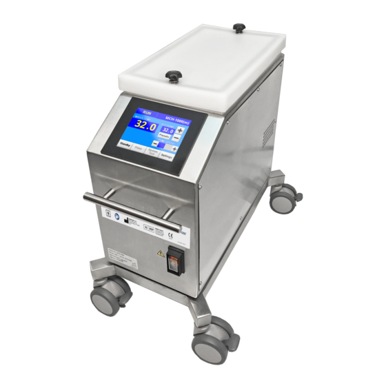
OVERVIEW In order to enjoy the greatest reliability from your MCH, please familiarize yourself with the essential parts and basic function of the device. MCH-1000(i) Hardware Overview Front: Back: Water Tank Cover Control Unit Control Unit Clamp Main Hose Connectors... -
Page 16: Operation Overview
Operation Overview The MCH operating software serves two basic functions. First, it provides an intuitive, feature- rich touchscreen control interface, giving the operator quick access to temperature settings, pump speed control, system test and status information, and customization features. Second, it constantly monitors the MCH’s internal systems to ensure that the hardware is functioning properly. -
Page 17: Control Screens
CONTROL SCREENS Power-on When the Mains Power Switch is first turned on, the CardioQuip logo will appear on the Control Unit screen along with the text, “Initializing...” to indicate that the MCH is booting. After approximately five seconds, the MCH will enter operational mode. -
Page 18: System Test
System Test On startup, the MCH enters TESTING mode and runs a system test to verify proper operation of all internal components. Onscreen indicator lamps display the status of control and feedback signals for the various internal systems, and the “Test Status” column (far right) displays the test results. -
Page 19: Standby
Standby System mode indicator Customizable text Current temperature display Temperature control buttons Operational indicators CPG option controls Pump speed control Control buttons In STANDBY mode, the pump and heaters are off, and the operator is able to preset the desired temperature and other settings in preparation for entering RUN mode. To set the desired temperature in tenth-degree increments, touch the temperature... -
Page 20: Priming
Priming System mode indicator Countdown timer Current Temperature display Extended Prime button CPG option controls Temperature control buttons Pump speed override Control buttons From the STANDBY screen, touch the button to enter PRIMING mode. While the MCH Prime is designed to be largely self-priming, running a priming cycle will remove all air bubbles from the lines, offering quieter operation and better heat transfer. -
Page 21: Settings
Low Ice alarm, set the number of available pump speeds, enable/disable the Auto Pump High feature, change the display language, and initiate the DEFROST cycle. System Time: Displays the number of hours and minutes the MCH-1000 has been in operation. Current Mode: Allows the operator to reduce the electrical current draw (e.g., when... -
Page 22: Defrost
Defrost The MCH incorporates a built-in defrost cycle, which utilizes the heaters in a special recirculating mode to melt the ice in the water tank. Once the water in the tank reaches room temperature, the MCH automatically returns to STANDBY mode. The DEFROST function is accessed from the SETTINGS screen. -
Page 23: Cardioplegia Shared Channel
Cardioplegia Shared Channel The CPG Module controls are only visible if the Cardioplegia Shared Channel Module (MCH-10CSC) is installed, and offer the following operational modes: Off Water does not flow through the CPG circuit. Water is circulated directly from the MCH water tank through the CPG circuit by a secondary water pump. -
Page 24: Alarms
ALARMS The MCH incorporates various alarms, enabling auditory monitoring of the system and alerting the operator to any conditions that require the operator’s attention. A low priority alarm alerts the operator to a condition that requires attention but poses minimal risk to the patient. -
Page 25: Overtemp (Medium Priority)
Overtemp (medium priority) Under normal operation, the MCH software will not allow the water temperature at the outlet to exceed 42.5˚C. If the outlet water temperature rises above 42.5˚C, the MCH halts its operation, the OVERTEMP screen appears, and the alarm sounds a repeating three-beep sequence every 8 seconds. -
Page 26: System Failure (Medium Priority)
MCH unit that could affect patient and operator safety. Even if the system returns to normal operation after a system test or a power cycle, please contact CardioQuip for troubleshooting assistance and, if necessary, to schedule a service call. -
Page 27: Setting The Temperature: 3 Ways
SETTING THE TEMPERATURE: 3 WAYS The set temperature can be adjusted from the STANDBY, RUN, or PRIMING screens. The MCH offers three different methods of adjusting the set temperature: Tenth-Degree Adjustment To set the desired temperature, from 0˚C to 42˚C in tenth-degree increments, touch the temperature control button. -
Page 28: Connectors, Valves, & Hoses
IN connector. Water at the OUT connector is under pressure when the system pump is on. These connectors are oriented horizontally on the MCH-1000(i), and vertically on the MCH-1000(m). MCH-1000(m) Main Hose Connections Connecting Hoses To connect a hose, firmly push the connector... -
Page 29: Cardioplegia Hose Connectors
Internal Recirculation Valve The internal recirculation valve is located on the rear panel of the MCH-1000(i), and allows the operator to stop water flow through external hoses, recirculating the water internally within the MCH. This may be useful for initial system priming (before hoses are connected), or preheating/precooling water during a procedure. -
Page 30: Blanket Hose Connectors
Blanket Hose Connectors The smaller connectors on the MCH-1000(i), directly below the “Main” connections on the rear panel of the MCH, are for connections to patient warming blankets. Maximum water flow at the blanket connectors is approximately 4 liters/min (1.0 gal/min). Approximate water flow when connected to a blanket is 1-2 liters/min. -
Page 31: System Drain
System Drain Tank Drain The tank drain valve is located on the front panel of the MCH-1000(i), and allows the operator to drain water from the water tank without draining the entire system. This may be useful e.g. to make room in the tank for more ice made with sterile or 0.22-micron filtered water during a procedure. -
Page 32: Hose Kits
MCH-11SHS), with dripless connectors at one end, nylon-reinforced PVC tubing, ball valves and a short section of flexible clear tubing at the oxygenator end. Standard lengths are 10ft (3m) for the MCH-1000(i) and 6ft (1.8m) for Standard Hose Kit the MCH-1000(m). -
Page 33: Tank Lid Anchor Knobs
Tank Lid Anchor Knobs The tank lid of the MCH-1000(m) includes a pair of spring- loaded anchoring knobs, which may be threaded onto posts to secure the lid onto the tank, in order to minimize water spillage while the MCH is being moved. To secure the lid, push down on the knob to engage the post, and turn the knob clockwise. -
Page 34: Patient Blankets
Any patient blanket used with the MCH must meet IEC 80601-2-35 standards for heating devices. CardioQuip has specifically tested the MCH with the Cincinnati Sub-Zero PlastiPad™ Reusable Plastic Blanket and Maxi-Therm™ Single Patient Use Blanket, and the Adroit Soft- Temp™... -
Page 35: Blanket Orientation
Blanket Orientation For most applications, CardioQuip recommends that the patient blanket be laid flat, without creases or wrinkles, between the bed or table and the patient, according to the diagram below. The blanket should be covered with a thin intermediate layer of insulating material, such as a sheet or thin blanket, to prevent patient discomfort and promote even heat transfer. -
Page 36: Optional Cooling Modules
CAUTION: Do not plug the TEC Module into the same electrical circuit as the MCH-1000(m). The TEC Module draws approximately 1.5 Amps of power, so it may be able to share a circuit with other equipment. The MCH-1000(m) requires a separate dedicated 20 Amp circuit (see Initial Operation Check). -
Page 37: Refrigeration Module
Refrigeration Module The Refrigeration Module (MCH-10RMS) replaces the lid on the MCH-1000(i) with an enclosed condensing unit that generates a block of ice in the tank. With room-temperature sterile or 0.22-micron filtered water in the tank, the Refrigeration Module will chill the water to 3˚C in about 75 minutes, and begin to make ice in about 1.5 hours. -
Page 38: Refrigeration Module Maintenance
(MCH-10ARH) may be installed to redirect the AIRFLOW AIRFLOW exhaust downward. Even with Airflow Redirection Hood installation, proper MCH MCH-1000 orientation should be followed to ensure exhaust air flows parallel to the operating table. During certain procedures—e.g., with a substandard surgical ventilation system, or with immunocompromised or infectious patients—it may be desirable to power off... -
Page 39: Airflow Redirection Hood
Airflow Redirection Hood The Airflow Redirection Hood (MCH-10ARH) redirects Refrigeration Module’s exhaust downward. This device is a possible risk mitigation component which redirects potential aerosols downwards and away from the surgical field. Airflow Redirection Hood MCH-10ARH Airflow Redirection Hood Installation 1. - Page 40 CAUTION: Do not plug the Refrigeration Module into the same electrical circuit as the MCH-1000(i). The Refrigeration Module draws approximately 6 Amps of power, so it may be able to share a circuit with other equipment. The MCH-1000(i) requires a separate dedicated 20 Amp circuit (see Initial Operation Check).
-
Page 41: Mch Operation
MCH OPERATION Unpacking Carefully inspect the shipping carton for damage. If damage has occurred, contact the carrier and request a damage report prior to opening the carton. Notation of damages with the delivery person will speed the filing of damage claims. CAUTION: Do not lift the MCH by the drain or water connections. -
Page 42: Initial Operation Check
Prior to operation in a clinical setting for the first time, or after extended storage, the following procedures should be performed. Contact CardioQuip if any failures are encountered. WARNING: It is the operator’s responsibility to use, check, and maintain this... -
Page 43: Mch-1000(I) Control Module Check
MCH-SCRN front panel of the MCH base unit. Basic Function Test 1. MCH-1000(i): Move the internal recirculation valve to the INTERNAL position and add approximately three gallons (12 liters) of sterile or 0.22-micron filtered water to the water tank. MCH-1000(m): Connect a loopback hose to the main hose connectors, and add approximately one gallon (4 liters) of sterile or 0.22-micron filtered water to the water tank. -
Page 44: Temperature Control System Test
Temperature Control System Test 1. From the STANDBY screen, set the temperature at 0°C, touch the button, and ensure the system enters cooling mode (water flows into the water tank, temperature control status reads “COOLING”). Note that the output temperature will only decrease to the nominal water temperature in the tank. -
Page 45: Terminating Operation
Terminating Operation button can be used to access the STANDBY screen, which stops the pump and Standby halts temperature control operations of the MCH. The mains power switch may be turned off at any time to completely terminate MCH operation. The set temperature and other operator-selectable settings are retained in the device’s memory. -
Page 46: Normal Operation
Contact CardioQuip Customer Service for details regarding servicing assistance. WARNING: If the external tubing appears cloudy or discolored, immediately remove the device from service and contact CardioQuip Customer Service for details regarding servicing assistance. WARNING: It is the operator’s responsibility to use, check, and maintain this... - Page 47 1. Attach the desired heat exchanger and/or blanket circuits to the appropriate connectors on the rear panel. 2. MCH-1000(i): Verify that the internal recirculation valve is in the NORMAL position. 3. Check the attached hoses to be sure there are no kinks, closed valves, etc. that would block water flow through the hose loop.
-
Page 48: Overtemp
11. If the water level in the tank is too high to accommodate additional ice, use the tank drain valve or the system drain to drain excess water from the water tank. Overtemp WARNING: If the unit is in an overtemp condition and the emergency cool system is used, it is critical that the operator monitor the output water temperature. -
Page 49: Maintenance
MAINTENANCE Deviation from maintenance procedures may result in increased patient risk. Water Quality The water in a cooler-heater can harbor various microorganisms commonly found in the hospital environment, some of which can pose health risks for immunocompromised individuals. The only effective way to control these risks is to closely monitor the water quality in the cooler-heater, use only sterile or 0.22-micron filtered water, and treat it like any other biohazardous material. -
Page 50: After Every Use
WARNING: The MCH must be disconnected from electrical power before inspecting, reprocessing, or preparing the device for use. CAUTION: Do not use acetone-based cleaning solutions to clean the MCH. Acetone-based cleaning solutions will cause equipment damage. CAUTION: Cleaning and disinfection policies and procedures must follow current FDA and CDC guidance. -
Page 51: Weekly Maintenance Procedure
WARNING: If the tubing appears cloudy or discolored during the External Tubing Inspection, immediately remove the device from service and contact CardioQuip Customer Service for details regarding servicing assistance. WARNING: If the water appears discolored, emits a foul smell, or shows visual signs of biofilm during the Water Quality Inspection, immediately remove the device from... -
Page 52: Quarterly Maintenance Procedure
MCH-1000(i) contains approximately three gallons (12 liters) of water, and the MCH-1000(m) contains approximately 1 gallon (4 liters) of water. 7. Run the MCH through five (5) standard priming cycles, or one extended priming cycle, to fully mix and circulate the cleaning chemical (10 minutes total). - Page 53 WARNING: Electric shock hazard. Access panels should be removed only by qualified service personnel. WARNING: If the tubing appears cloudy or discolored during the internal tubing Inspection, immediately remove the device from service and contact CardioQuip Customer Service for details regarding servicing assistance. MAINTENANCE | Quarterly Maintenance Procedure...
-
Page 54: Annual Maintenance
Annual Maintenance The MCH shall receive a complete preventive maintenance service check by an authorized CardioQuip service technician every 12 months. CardioCare annual preventive maintenance service is available for purchase at www.cardioquip.com/cardiocare. Exterior tubing from the hose kits must be replaced every 2 years regardless of condition. -
Page 55: Troubleshooting
If the breaker immediately trips, have qualified service personnel check for a direct short. Contact CardioQuip Service. Faulty mains power switch Faulty temperature control Contact CardioQuip Service. circuitry System will not Have qualified service personnel check... - Page 56 Clogged quick-disconnect coupling external coupling connected. Using or tubing compressed air, force the blockage out. Faulty quick disconnect coupler Contact CardioQuip Service. Place system in PRIMING mode according Pump not primed to operating instructions. Clean mesh strainers at the bottom of the Blockage in water tank water tank with a nylon brush.
- Page 57 Immediately remove the device from Cloudy or discolored exterior tubing may have service and contact CardioQuip Customer hoses undergone physical changes. Service regarding servicing assistance. If the above table does not address the problem, please contact CardioQuip Service for assistance: www.cardioquip.com/service...
-
Page 58: Wiring Schematics
Wiring Schematics MCH-1000(i) - Page 59 Wiring Schematics MCH-1000(m)
Need help?
Do you have a question about the MCH-1000 and is the answer not in the manual?
Questions and answers