
Related Manuals for Burkert SideControl BASIC


Summary of Contents for Burkert SideControl BASIC
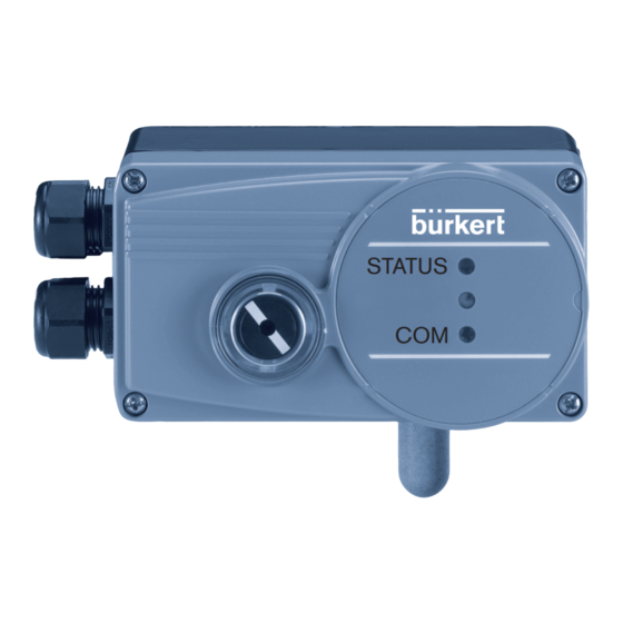
- Page 1 Type 8791 REV.2 Positioner SideControl BASIC Electropneumatic positioner Elektropneumatischer Positioner Positionneur électropneumatique STATUS Quickstart English / Deutsch / Français...
- Page 2 We reserve the right to make technical changes without notice. Technische Änderungen vorbehalten. Nous nous réservons le droit d’apporter des modifications techniques sans préavis. © Bürkert Werke GmbH & Co. KG, 2009 - 2022 Operating Instructions 2211/04_EUml_00815311 / Original DE...
-
Page 3: Table Of Contents
Type 8791 REV.2 Type 8791 positioner REV.2 ATTACHMENT AND ASSEMBLY ........... 17 8.1 Installation of devices for the Ex area ....... 17 ABOUT THESE INSTRUCTIONS .......... 4 8.2 Attachment to a continuous valve with linear Symbols ............... 4 actuators according to NAMUR ........ 17 1.2 Definition of terms ............5 8.3 Attachment to a continuous valve with rotary actuator ............21 INTENDED USE ..............5 8.4 Remote operation with external position sensor .. -
Page 4: About These Instructions
→ Keep these instructions ready to hand at the operation site. Important safety information. ▶ Carefully read these instructions. ▶ Observe in particular the safety instructions, intended use and operating conditions. ▶ Persons, who work on the device, must read and understand these instructions. The operating instructions can be found on the Internet at: country.burkert.com Symbols DANGER! Warns of an immediate danger. ▶ Failure to observe the warning may result in a fatal or serious injury. WARNING! Warns of a potentially dangerous situation. ▶ Failure to observe the warning may result in serious or fatal injuries. -
Page 5: Definition Of Terms
Type 8791 REV.2 Intended use INTENDED USE CAUTION! The Positoner Type 8791 REV.2 is designed to be mounted arns of a possible danger. on pneumatic actuators of process valves for the control of ▶ Failure to observe the warning may result in moderate or minor media. The permitted fluid media are listed in the technical injuries. -
Page 6: Basic Safety Instructions
Type 8791 REV.2 Basic safety instructions BASIC SAFETY INSTRUCTIONS ▶ Do not feed corrosive or flammable media into the device connections. These safety instructions do not consider any contingencies or inci- ▶ Do not feed any fluids into the connections of the device. dents which occur during installation, operation and maintenance. ▶ After the process is interrupted, restart in a controlled man- The operator is responsible for observing the location-specific safety ner. Observe sequence: regulations, also with reference to the personnel. 1. Connect electrical or pneumatic power supply. 2. Charge the device with medium. ▶ Observe intended use. Risk of injury from high pressure and discharge of medium. ▶ Before working on the device or system, switch off the pres- NOTE! sure. Vent or drain lines. Electrostatic sensitive components or modules. Risk of injury from electric shock. -
Page 7: General Notes
GENERAL NOTES PRODUCT DESCRIPTION Contact address Structure Germany Mechanical position indicator Bürkert Fluid Control Systems Sales Centre Display module with 2 LEDs Christian-Bürkert-Str. 13–17 D-74653 Ingelfingen Tel. +49 (0) 7940 - 10 91 111 Fax +49 (0) 7940 - 10 91 448 Email: info@burkert.com International Working connection 2 The contact addresses can be found on the back pages of the (connection: A2) printed quickstart. Supply pressure Also on the Internet at: country.burkert.com connection 1.4 – 7 bar Warranty (connection: P) A precondition for the warranty is that the Type 8694 positioner Working connection 1 is used as intended in consideration of the specified operating (connection: A1) conditions. -
Page 8: General Description
Type 8791 REV.2 Technical data TECHNICAL DATA Electronic module Standards and directives The device complies with the relevant EU harmonisation legis- Internal position sensor lation. In addition, the device also complies with the require- ments of the laws of the United Kingdom. Pilot valve system The harmonised standards that have been applied for the con- formity assessment procedure are listed in the current version of the EU Declaration of Conformity/UK Declaration of Conformity. Axle for position sensor Operating conditions WARNING! Cable gland Solar radiation and temperature fluctuations may cause mal- Fig. 2: Structure, positioner Type 8791 functions or leaks. General description ▶... -
Page 9: Mechanical Data
Type 8791 REV.2 Technical data Mechanical data Electrical data Dimensions See data sheet 6.5.1 Electrical data, without field bus communication Material Protection class I II in accordance with DIN EN 61140 H ousing material Plastic-coated aluminium (VDE 0140-1) Other external parts S tainless steel (V4A), PC, PE, POM, PTFE Connections 2 cable glands (M20 x 1.5) with screw- type terminals 0.14 – 1.5 mm or circular Sealing material EPDM, NBR, FKM plug-in connector (M12, 8-pin plug) Weight approx. 1.0 kg Operating voltage 2 4 V DC ±25 %, max. residual ripple 10% Type label... -
Page 10: Pneumatic Data
Type 8791 REV.2 Technical data 6.5.2 Electrical data, IO-Link 6.5.3 Electrical data, büS Protection class I II as per DIN EN 61140 Protection class I II as per DIN EN 61140 (VDE 0140-1) (VDE 0140-1) Connection C ircular plug-in connector M12 x Connection C ircular plug-in connector M12 x 1, 1, 5-pin, A-coded 5-pin, A-coded Port Class A Operating voltage 2 4 V DC ±25 % (according to specification) Operating voltage 24 V DC ±25% (according to specifications) Current consumption max. 150 mA Current consumption max. 150 mA... -
Page 11: Operating
Type 8791 REV.2 Operating Air flow rate OPERATING Universal 50 l /min (at 1.4 bar ) for aeration Operating state Air flow rate and ventilation Single and 150 l /min (at 6 bar ) for aeration AUTOMATIC (AUTO) and double acting ventilation Normal controller mode is implemented and monitored in AUTO- = 100 l /min (according to MATIC operating state. definition with pressure drop from MANUAL 7 to 6 bar absolute) In MANUAL operating state the valve can be opened and closed Low air flow rate = 7 l /min (according to defnition manually via the buttons. with Single-acting pressure drop from 7 to 6 bar absolute) To operate the DIP switches and buttons, make sure that the local control lock is deactivated/unlocked (factory Connections... -
Page 12: Operating And Display Elements Of The Positioner
Type 8791 REV.2 Operating Operating and display elements of the 7.2.1 Configuration of the buttons positioner To operate the DIP switches and buttons, make sure that the local control lock is deactivated/unlocked (factory To operate the DIP switches and buttons, make sure that setting): with communication software or fieldbus the local control lock is deactivated/unlocked (factory communication. setting): with communication software or fieldbus communication. The configuration of the 2 buttons inside the housing varies depending on the operating state (AUTOMATIC / MANUAL). Button 1 The description of the operating state (AUTOMATIC / MANUAL) can be found in the chapter entitled “7.1 Operating state”. DIP Switches LED 1 LED 2 Button 1 Button 2 Button 2... - Page 13 Type 8791 REV.2 Operating MANUAL operating state (DIP switch 4 set to ON): 7.2.2 Function of the DIP switches Button Function Function switches Aerate (manually open / close the actuator) 1 2 3 4 Reversal of the effective direction of the set-point Deaerate (manually open / close the actuator) value (20 – 4 mA corresponds to 0 – 100 %), Longer than 10 s (< 30 s, LED 2 flashes at 5 Hz): descending (DIR.CMD) 1 and 2 Device restart Normal effective direction of the set-point value simulta- (4 – 20 mA corresponds to 0 – 100 %), ascending Longer than 30 s (LED 2 flashes at 10 Hz): neously Reset device to factory setting Sealing function active. The valve completely Tab. 1: Configuration of the buttons for MANUAL operating state closes below 2 % and opens above 98 % of the set-point value (CUTOFF)
- Page 14 Type 8791 REV.2 Operating 7.2.4 Device status display Information about the communications software: The switching position of the DIP switch has priority The LED 1 (RGB) show the device status. over the communications software. The user can set the following LED modes for the display of If the values of the sealing function (CUTOFF) or the device status and valve position. correction characteristic (CHARACT) are changed via the •...
- Page 15 Type 8791 REV.2 Operating 7.2.5 Valve mode + warnings (factory setting) If several device statuses exist simultaneously, the device status with the highest priority is displayed. Displays in valve mode + warnings: • Valve position: open, half-way, closed Valve Device status • Device status: failure, function check, out of specification, position Out of Mai n tenance Failure Function maintenance required (according to NAMUR) check specifi- required cation Valve position Device status Status, Status, Status, Status, Status, color Normal operation color...
- Page 16 Type 8791 REV.2 Operating 7.2.6 NAMUR mode Status indicator in line with NE 107, issue 2006-06-12 The LED 1 show the device status. Colour Colour Status Description The display elements change color in accordance with NAMUR code NE 107. Green 1 Diagnostics Device is in error-free operation. If several device statuses exist simultaneously, the device status active Status changes are highlighted in with the highest priority is displayed. The priority is determined colour. by the severity of the deviation from controlled operation (red Messages are sent via any fieldbus LED = failure = highest priority). that may be connected. Tab. 6: Description of colour Status display in accordance with NE 107, edition 2006-06-12 Color Color...
-
Page 17: Attachment And Assembly
Type 8791 REV.2 Attachment and assembly ATTACHMENT AND ASSEMBLY Part no. Quantity Name Installation of devices for the Ex area NAMUR mounting bracket IEC 534 When installing devices in the potentially explosive atmosphere, Hoop observe the “Additional information for use in the Ex area“ enc- Clamping piece losed with the Ex-devices. Driver pin Attachment to a continuous valve with Conical roller linear actuators according to NAMUR NAMUR lever for stroke range 3 – 35 mm The valve position is transferred to the position sensor installed NAMUR lever for stroke range 35 – 130 mm in the positioner via a lever (according to NAMUR). - Page 18 Type 8791 REV.2 Attachment and assembly 8.2.1 Installation → Select short or long lever according to the stroke of the actuator (see “Tab. 8: Attachment kit for linear actuators”, WARNING! part no. 6a/6b). → Assemble lever (if not pre-assembled) (see “Fig. 8”). Risk of injury from improper installation. ▶ Installation may be carried out by authorised technicians only and with the appropriate tools. Risk of injury from unintentional activation of the system and an uncontrolled restart. ▶ Secure system from unintentional activation. 16 16 ▶...
- Page 19 Type 8791 REV.2 Attachment and assembly The gap between the driver pin and the axle should be the same as the drive stroke. This results in the ideal angular range of the lever of 60° (see “Fig. 9”). 120° Maximum rotational Angular range of the position sensor: range of the lever The maximum angular range of the position sensor is 180°. Rotational range of the lever: Rotational range of To ensure that the position sensor operates at a good the lever resolution, the rotational range of the lever must be Ideal: 60° between 30° and 120°. Minimum: 30° Maximum: 120° The scale printed on the lever is not relevant. Fig. 9: Rotational range of the lever ⑰...
- Page 20 Type 8791 REV.2 Attachment and assembly 8.2.2 Attaching mounting bracket Attaching the positioner with mounting bracket for actuators ① with cast frame: → Attach mounting bracket to the back of the positioner ⑨ ⑩ ⑪ → Attach mounting bracket to the cast frame with one or more with hexagon bolts , circlip and washers (see “Fig. ⑧ ⑪ ⑩ hexagon bolts , washers and circlips (see “Fig. 10”).
-
Page 21: Attachment To A Continuous Valve With Rotary Actuator
Type 8791 REV.2 Attachment and assembly Attachment to a continuous valve with Attaching the positioner with mounting bracket for actuators with columnar yoke: rotary actuator → Attach mounting bracket to the columnar yoke with the U-bolt The axle of the position sensor integrated in the positioner is ⑦ ⑪ ⑩ , washers , circlips and hexagon nuts (see “Fig. connected directly to the axle of the rotary actuator. 12”). The assembly bridge can be purchased from Bürkert as an accessory by quoting the identification number 770294. The attachment kit for the rotary actuators can be purchased from Bürkert as an accessory by quoting the identification number 787338. - Page 22 Type 8791 REV.2 Attachment and assembly 8.3.1 Installation Angular range of the position sensor: The maximum angular range of the position sensor is WARNING! 180°. The axis of the positioner should only be used within this range. Risk of injury from improper installation. ▶ Installation may be carried out by authorised technicians 180° only and with the appropriate tools. Maximum rota- Risk of injury from unintentional activation of the system and tional range an uncontrolled restart. ▶...
- Page 23 Type 8791 REV.2 Attachment and assembly ① ④ ③ Fig. 15: Rotary actuator attachment Fig. 14: Attaching assembly bridge (schematic representation) → Place the positioner with the assembly bridge on the rotary actuator and attach it using four hexagon bolts (see “Fig. 15”). english...
-
Page 24: Remote Operation With External Position Sensor
Type 8791 REV.2 Attachment and assembly Remote operation with external 8.4.2 Connection and start-up of the remote sensor Type 8798 position sensor In this variant, the positioner does not have a position sensor in WARNING! the form of an angle of rotation sensor but has an external remote sensor. Risk of injury due to improper start-up. The Type 8798 remote sensor is connected using a serial digital ▶ Start-up may be carried out by authorised technicians only interface. and with the appropriate tools. Risk of injury due to unintentional activation of the system and uncontrolled restart. -
Page 25: Pneumatic Connection
Type 8791 REV.2 Pneumatic connection PNEUMATIC CONNECTION Connection of devices for Ex areas For connection in potentially explosive atmospheres, the “Addi- tional information for use in potentially explosive atmospheres” enclosed with the device must be adhered to. Working port 2 (Connection: A2) Safety instructions Pressure port 1.4...7 bar (Connection: P) DANGER! Working port 1 Risk of injury from high pressure in the system/device. (Connection: A1) ▶ Before working on the system or device, switch off the pressure Exhaust port and vent/empty the lines. Fig. 17: Pneumatic installation/location of connections WARNING! Procedure: Risk of injury due to improper installation. -
Page 26: Safety End Positions
Type 8791 REV.2 Pneumatic connection Safety end positions For double-acting actuators (control function I): → Connect working ports A1 and A2 to the respective chamber The safety end position after the electrical auxiliary power fails of the double-acting actuator. depends on the fluidic connection of the actuator to the working For safety end positions see Chapter “9.3 Safety end ports A1 or A2. positions”. 9.3.1 Single-acting actuators Important information for perfect control behaviour! Safety end positions after failure of To prevent the control behaviour in the upper stroke range Actuator type from being negatively influenced by a small pressure electrical auxi- pneumatic difference... - Page 27 Type 8791 REV.2 Pneumatic connection 9.3.2 Double-acting actuators Single-acting actuators - control function A or B Safety end positions after failure of the Actuator type electrical auxi- pneumatic liary power auxiliary power → Connection Upper see “Fig. 20” chamber Lower up = lower chamber chamber of the not defined actuator on A2 Connect working port A1 Connect working port A2 to the actuator to the actuator...
-
Page 28: Electrical Connection
Type 8791 REV.2 Electrical connection ELECTRICAL CONNECTION 10.3 Electrical installation without fieldbus communication All electrical inputs and outputs of the device are not galvanically isolated to the supply voltage. 10.3.1 Electrical installation with circular plug-in connector M12, 8-pin 10.1 Connection of devices for Ex areas For connection in potentially explosive atmospheres, the “Addi- tional information for use in potentially explosive atmospheres” Supply voltage enclosed with the device must be adhered to. and various signals 10.2 Safety instructions DANGER! Risk due to electric shock. ▶... - Page 29 Type 8791 REV.2 Electrical connection Pin assignment for operating voltage Pin assignment for the output signals to the control centre (only analogue output variant) Pin Wire Assignment External circuit/signal level colour Pin Wire Assignment Device External circuit/signal colour level 24 V DC ±25% green Analogue + (0/4...20 mA) max. residual ripple 10%...
- Page 30 Type 8791 REV.2 Electrical connection 10.3.2 3 conductor or 4 conductor connection 3 conductor connection type type The setpoint input is linked to the GND line of the supply Configuration with communication software voltage, i.e. setpoint input and supply voltage share a GND line. 4 conductor connection type (factory setting) The setpoint input is designed as a differential input, i.e. the “11+” GND lines of the setpoint input and the supply voltage are not Pin 1 0/4...20 mA identical. Note: if the GND signals of the setpoint input and the supply voltage are connected, the 3 conductor connection type must “GND” be set in the software. Pin 3 +24 V DC “11+” “+24 V” Pin 1 Pin 4 0/4...20 mA...
- Page 31 Type 8791 REV.2 Electrical connection 10.3.4 Connection of terminals 10.3.3 Electrical installation with cable gland → Unscrew the 4 screws on the housing lid and remove the housing lid. 11 + The screw-type terminals are now accessible. 12 – → Connect terminals according to the pin assignment. Terminal assignment for input signals from control centre (e.g. PLC) 31 + 32 – Clip Assignment Device end External circuit/signal level 11 + Set-point 11 +...
- Page 32 Type 8791 REV.2 Electrical connection 10.3.5 Terminal assignment for external position Terminal assignment for the output signals to the control centre (only analogue output variant) sensor (only remote variant) Device Clip Assignment Device end External circuit/signal Clip Assignment External circuit/signal level level Sensor 31 +...
-
Page 33: 10.4 Electrical Installation, Io-Link
Type 8791 REV.2 Electrical connection 10.4 Electrical installation, IO-Link You can find the pin assignment of the remote variant in the chapter “10.6” 10.5 Electrical installation, büS M8 socket, 4-pin M12 plug x 1, 5-pin (remote variant only) Fig. 23: Pin assignment M8 socket, 4-pin M12 plug x 1, 5-pin Pin assignment port class A (remote variant only) Fig. 24: Pin assignment Designation Assignment 24 V DC System supply Wire colour Assignment Not used CAN label/shielding CAN label/shielding... -
Page 34: Connection Assignment For External Position Sensors (Remote Variant)
Type 8791 REV.2 Start-up START-UP You can find the pin assignment of the remote variant in the chapter “10.6” 11.1 Safety instructions 10.6 Connection assignment for external WARNING! position sensors (remote variant) Risk of injury due to improper operation. Assignment Device end External circuit Improper operation may result in injuries as well as damage to the device and the area around it. Sensor Remote ▶ Before start-up, ensure that the operating personnel are supply + sensor aware of and have completely understood the contents of Sensor Type 8798 the operating instructions. - Page 35 Type 8791 REV.2 Start-up 11.2.1 Perform the X.TUNE automatic adjustment If X.TUNE has been successfully complete, the NAMUR state is reset. The changes are automatically adopted in the memory WARNING! (EEPROM). Risk from changing the valve position when executing the If LED 1 lights red after X.TUNE: X.TUNE function. → Execute X.TUNE again. If X.TUNE is operated under operating pressure there is an → Perform device restart if necessary. acute risk of injury. ▶ Never execute X.TUNE when a process is running. ▶ Secure the system against unintentional activation. NOTE! Faulty adjustment of the controller may occur if the pilot pressure is incorrect or the operating pressure is applied to the valve seat.
-
Page 36: Set Device With Bürkert Communicator
Type 8791 REV.2 Start-up 11.3 Set device with Bürkert Key 1 Communicator DIP switch LED 1 All settings can be made on the device with Bürkert LED 2 Communicator. You can find the settings in Bürkert Communicator in the operating instructions. 11.3.1 Connecting the IO-Link device to the Bürkert Communicator Necessary components: Key 2 • Communication software: Bürkert Communicator for PC Communication interface • USB büS interface set (see accessories) Fig. 25: Description of operating elements •... -
Page 37: Büs
Type 8791 REV.2 Start-up IO-Link is a point-to-point communication system with 3-wire 11.4.3 Configuring the fieldbus connection technology for sensors and actuators and unshielded The necessary start-up files and the description of the process standard sensor lines. data and acyclic parameters are available online. To ensure unambiguous communication, IO-Link devices should Download at: not be configured simultaneously using the global controller www.burkert.com/Type 8791/Software (PLC) via the IO-Link master and using the Bürkert Communi- cator (via the service interface). 11.5 büS 11.5.1 Information, büS 11.4.2 Technical data, IO-Link büS is a system bus developed by Bürkert. The communication IO-Link specification V1.1.2 protocol is based on CANopen. Supply v ia IO-Link (M12 x 1, 5-pin, A-coded) 11.5.2 Configuring the fieldbus... - Page 38 Accessories ACCESSORIES 12.1 Communication software The Bürkert Communicator PC operating program has been Designation Order no. designed for communication with devices from the Bürkert posi- tioner family. Connection cable M12, 8-pin 919061 Please contact the Bürkert Sales Center for compatibility questions. Bürkert Communicator communication Info at software country.burkert.com A detailed description of the installation and operation of the software can be found in the associated operating instructions. USB büS interface set: Download the software from: country.burkert.com USB büS interface set 2 (büS stick + 0.7 m 772551 cable with M12 plug) büS adapter for communication interface 773254 (M12 to büS service interface micro-USB) büS cable extension (M12), length 1 m 772404 büS cable extension (M12), length 3 m 772405 büS cable extension (M12), length 5 m...
- Page 39 Transport damage. Inadequately protected devices may be damaged during transport. ▶ Use shock-resistant packaging to protect the device against moisture and dirt during transport. ▶ Avoid exceeding or dropping below the permitted storage temperature. ▶ Protect pneumatic connections from damage with protective caps. Incorrect storage may damage the device. ▶ Store the device in a dry and dust-free location. ▶ Storage temperature –20...+65 °C. Environmentally friendly disposal ▶ Follow national regulations regarding disposal and the environment. ▶ Collect electrical and electronic devices separa- tely and dispose of them as special waste. Further information country.burkert.com. english...
- Page 41 www.burkert.com...
Need help?
Do you have a question about the SideControl BASIC and is the answer not in the manual?
Questions and answers