Burkert 8791 Operating Instructions Manual
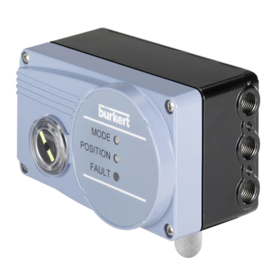
Positioner sidecontrol basic
electropneumatic positioner
Hide thumbs
Also See for 8791:
- Operating instructions manual (186 pages) ,
- Quick start manual (38 pages) ,
- Assembly instructions manual (16 pages)

Subscribe to Our Youtube Channel
Related Manuals for Burkert 8791


Summary of Contents for Burkert 8791
- Page 1 Type 8791 Positioner SideControl BASIC Electropneumatic positioner Operating Instructions...
- Page 2 We reserve the right to make technical changes without notice. Technische Änderungen vorbehalten. Sous réserve de modifications techniques. © Bürkert Werke GmbH & Co. KG, 2009 – 2018 Operating Instructions 1802/08_EU-EN_00805664 / Original DE...
-
Page 3: Table Of Contents
Type 8791 Electropneumatic positioner Type 8791 ontents OPERATING INSTRUCTIONS ........................8 Symbols ............................8 1.2 Definition of term / abbreviation ....................8 AUTHORIZED USE ..........................9 BASIC SAFETY INSTRUCTIONS ......................10 GENERAL INFORMATION ........................11 4.1 Contact addresses ........................11 4.2 Warranty .............................11 4.3 Information on the Internet ......................11 DESCRIPTION OF SYSTEM .........................12 5.1 General description ........................12 5.1.1 Features ........................12 5.1.2... - Page 4 Type 8791 8.2 Standards ...........................22 8.3 Operating conditions .........................22 8.4 Mechanical data .........................22 8.5 Electrical data ..........................23 8.5.1 Electrical data 24 V DC ....................23 8.5.2 Electrical data with AS-Interface bus control (optional) ..........23 8.6 Pneumatic data ..........................24 8.7 Safety end positions after failure of the electrical or pneumatic auxiliary power ....25 8.8 Factory settings of the positioner .....................26 8.8.1 Functions can be activated via DIP switches .............26...
- Page 5 Type 8791 10.2 Additional functions ........................39 10.2.1 DIR.ACTUATOR - Effective direction of the actuator ................39 10.2.2 SPLITRANGE - Signal split range ......................40 10.2.3 X.LIMIT - Limiting the mechanical stroke range .................41 10.2.4 X.TIME - Limiting the control speed ..................42 10.2.5 X.CONTROL - Parameterization of the positioner ................43 10.2.6...
- Page 6 Type 8791 13.2 Electrical connection with circular plug-in connector .............59 13.2.1 Designation of the circular plug-in connector ............59 13.2.2 Pin assignment for input signals from the control centre (e.g. PLC) - M12, 8-pole plug........................60 13.2.3 Pin assignment for output signals to the control centre (e.g. PLC) - M12, 8-pole plug (required for analogue output option only) ..........60...
- Page 7 Type 8791 PACKAGING AND TRANSPORT ......................71 STORAGE .............................71 DISPOSAL ............................71 english...
-
Page 8: Operating Instructions
→ Designates a procedure that must be carried out. Definition of term / abbreviation The term “device” used in these instructions always stands for the positioner type 8791. In these instructions, the abbreviation “Ex” always refers to “potentially explosive”. english... -
Page 9: Authorized Use
▶ Do not expose the device to direct sunlight. ▶ Pulsating direct voltage (rectified alternating voltage without smoothing) must not be used as supply voltage. ▶ In the potentially explosion-risk area the positioner type 8791 may be used only according to the speci- fication on the separate Ex rating plate. For use observe the additional information enclosed with the device together with safety instructions for the explosion-risk area. -
Page 10: Basic Safety Instructions
Type 8791 Basic Safety Instructions BASIC SAFETY INSTRUCTIONS These safety instructions do not make allowance for any • contingencies and events which may arise during the installation, operation and maintenance of the devices. • local safety regulations – the operator is responsible for observing these regulations, also with reference to the installation personnel. -
Page 11: General Information
Fax + 49 (0) 7940 - 10 91 448 E-mail: info@buerkert.com International Contact addresses can be found on the final pages of these printed operating instructions. And also on the internet at: www.burkert.com Warranty The warranty is only valid if the positioner Type 8791 are used as intended in accordance with the specified application conditions. Information on the Internet The operating instructions and data sheets for Type 8791 can be found on the internet at: www.burkert.com english... -
Page 12: Description Of System
Type 8791 Description of System DESCRIPTION OF SYSTEM General description The positioner Type 8791 is a digital, electropneumatic positioner for pneumatically actuated proportional valves. The device incorporates the main function groups - Position sensor - Electropneumatic control system - Microprocessor electronics The position sensor measures the current positions of the proportional valve. -
Page 13: Combination With Valve Types And Mounting Versions
Optionally external position feedback with inductive proximity switch The positioner type 8791 can be fitted with an external position feedback (see data sheet / accessories). The installation and the setting are described in the installation instructions which are enclosed with the external position feedback. The installation instructions can also be found on the Internet. www.burkert.com → Type 8791 english... -
Page 14: Overview Of The Mounting Options
Type 8791 Description of System 5.1.4 Overview of the mounting options Mounting NAMUR on rotary actuator Mounting NAMUR with mounting bracket on a linear actuator Remote mounting with mounting bracket Remote mounting with DIN rail Table 1: Overview of the mounting options... -
Page 15: Structure
Type 8791 Structure STRUCTURE The positioner Type 8791 consist of the micro-processor controlled electronics, the position sensor and the control system. The appliance is designed using three-wire technology. The unit is operated via 2 keys and 4 DIP switches. 3 LEDs indicate the different statuses of the unit. -
Page 16: Function
Diagram illustrating single-acting actuator Compressed-air Control valve with supply Positioner Type 8791 single-acting actuator Position set- point value Positioner Control system* Exhaust air Position sensor Actual position * Control system 1: Aeration valve 2: Bleed valve Figure 2: Function diagram, positioner type 8791 The remote design has the position sensor situated outside the positioner directly on the propor- tional valve and is connected to the latter by a cable. english... -
Page 17: Function Of The Position Control
Type 8791 Function Function of the position control The position sensor records the current position (POS) of the pneumatic actuator. The positioner compares this actual position value with the set-point value (CMD) which is a standard signal. If there is a control difference (Xd1), the actuator is aerated and deaerated via the control system. In this way the position of the actuator is changed until control difference is 0. Z1 represents a disturbance variable. -
Page 18: Schematic Representation Of The Position Control
Type 8791 Function Schematic representation of the position control * Can be activated with communica- tions software only Figure 4: Schematic representation of position control english... -
Page 19: Properties Of The Positioner Software
Type 8791 Function Properties of the positioner software 7.4.1 Functions I • Activation via DIP switches • Parameter setting via communications software Additional function Effect Sealing function Valve closes tight outside the control range. Speci- fication of the value (as %) from which the actuator CUTOFF is completely deaerated (when 0%) or aerated (when 100%) (see chapter entitled “9.3.2 Function of the DIP switches”). -
Page 20: Functions Ii
Type 8791 Function 7.4.2 Functions II • Activation and parameter setting via communications software Additional function Effect Standard signal for set-point value Select set-point value standard signal. INPUT Effective direction of the actuator Assignment of the aeration state of the actuator chamber to the actual position. -
Page 21: Interfaces Of The Positioner
Type 8791 Function Interfaces of the positioner Input for Analog position set-point value * feedback 4 – 20 mA ** (optional) Positioner 0 – 20 mA Proximity switch 1 / Binary input Proximity switch 2 24 V PNP NO (optional) -
Page 22: Technical Data
(only if cables, plugs and sockets have been connected correctly) 2) If the positioner is used under IP67 conditions, the ventilation filter (see “Figure 1: Structure, positioner type 8791”) must be removed and the exhaust air conducted into the dry area. -
Page 23: Electrical Data
Type 8791 Technical data Electrical data 8.5.1 Electrical data 24 V DC Connections 2 cable glands (M20 x 1.5) with screw-type terminals 0.14 – 1.5 or circular plug-in connector (M12, 8 pole plug) Interfaces Communications interface USB: Direct connection to PC via USB adapter. -
Page 24: Pneumatic Data
Type 8791 Technical data Pneumatic data Control medium Neutral gases, air Quality classes in accordance with ISO 8573-1 Dust content Quality class 7 max. particle size 40 µm, max. particle density 10 mg/m³ Water content Quality class 3 max. pressure dew point - 20 °C or min. 10 degrees... -
Page 25: Safety End Positions After Failure Of The Electrical Or Pneumatic Auxiliary Power
Type 8791 Technical data Safety end positions after failure of the electrical or pneumatic auxiliary power The safety end position depends on the fluid connection of the actuator to the working connections A1 or A2. Safety end positions after failure of the Actuator system Designation pneumatic electrical auxiliary power auxiliary power down single-acting → Connection according to “Figure 6” down Control function down → Connection according to “Figure 7”... -
Page 26: Factory Settings Of The Positioner
Type 8791 Technical data Factory settings of the positioner 8.8.1 Functions can be activated via DIP switches Function Parameter Value CUTOFF Sealing function below 98 % Sealing function above CHARACT Select characteristic FREE DIR.CMD Effective direction set-point value increasing Table 5: Factory settings; Functions can be activated via DIP switches 8.8.2... -
Page 27: Operating
Type 8791 Operating OPERATING Safety instructions WARNING! Risk of injury from improper operation! Improper operation may result in injuries as well as damage to the unit and the area around it. ▶ The operating personnel must know and have understood the contents of the operating instructions. -
Page 28: Configuration Of The Keys
Type 8791 Operating 9.3.1 Configuration of the keys The configuration of the 2 keys inside the housing varies depending on the operating status (AUTOMATIC / MANUAL). The description of the operating status (AUTOMATIC / MANUAL) can be found in the chapter entitled “9.2 Operating status”. Key 1 Key 2 Figure 10: Description of the keys MANUAL operating status (DIP switch 4 set to ON):... -
Page 29: Function Of The Dip Switches
Type 8791 Operating 9.3.2 Function of the DIP switches 1 2 3 4 DIP Switches Position Function Reversal of the effective direction of the set-point value (DIR. CMD) (set-point value 20 – 4 mA corresponds to position 0 – 100%) Normal effective direction of the set-point value (set-point value 4 – 20 mA corresponds to position 0 – 100%) Sealing function active. The valve completely closes below 2% and opens above 98% of the set-point value (CUTOFF) No sealing function Correction characteristic for adjustment of the operating charac- teristic (Linearization of the operating characteristic CHARACT) -
Page 30: Display Of The Leds
Type 8791 Operating 9.3.3 Display of the LEDs LED 1, green (MODE) Display of AUTO, MANUAL, X.TUNE LED 2, green / yellow (POSITION) Display of actuator status (open, closed, opens or closes) LED 3, red (FAULT) Error status Figure 11:... -
Page 31: Error Messages
Type 8791 Operating Error messages 9.4.1 Error messages in MANUAL and AUTOMATIC operating status Display Cause of fault Remedial action LED 3 (red, Checksum error in data memory not possible, device defective. FAULT) on → Data memory defective Contact your Bürkert sales office. → The device automatically switches to an older (possibly not current) data record. -
Page 32: Functions
Type 8791 Functions FUNCTIONS The positioner type 8791 has different basic and additional functions which can be configured and param- eterized via the DIP switches or the communications software. 10.1 Basic functions The following basic functions can be activated via the DIP switches (CUTOFF and CHARACT) or changed (DIR.CMD). Function Description DIP switches OFF DIR.CMD Effective sense of direction... -
Page 33: Dir.cmd
Type 8791 Functions 10.1.1 DIR.CMD - Effective sense of direction of the positioner set-point value Use this function to set the effective sense of direction between the input signal (INPUT) and the set-point position of the actuator. Factory settings: DIP switch set to OFF (ascending) DIP switches Position Function Reversal of the effective sense of direction of the set-point value (DIR.CMD) Set-point value (20 – 4 mA corresponds to position 0 – 100 %), descending Normal effective sense of direction of the set-point value (Set-point value 4 – 20 mA corresponds to position 0 – 100 %), ascending Table 16: DIP switches 1 The effective sense of direction (DIR.CMD) can be changed only via DIP switch 1 in the positioner. -
Page 34: Cutoff
Type 8791 Functions 10.1.2 CUTOFF - Sealing function for the positioner This function causes the valve to be sealed outside the control range. Controlled operation is resumed with a hysteresis of 1 %. Factory settings: DIP switch 2 set to OFF (no sealing function) DIP switches Position Function Sealing function active. The valve completely closes below 2... -
Page 35: Charact
Type 8791 Functions 10.1.3 CHARACT - Transfer characteristic between input signal (position set-point value) and stroke Characteristic (customer-specific characteristic) This function can be used to activate a transfer characteristic with respect to set-point value (set-point position) and valve stroke for correction of the flow or operating characteristic. The transfer characteristic can be changed via the communications software only. Factory settings: DIP switch 3 set to OFF (linear) - Page 36 Type 8791 Functions The flow characteristic k = f(s) indicates the flow-rate of a valve, expressed by the value k as a function of the stroke s of the actuator spindle. It is determined by the design of the valve seat and the seat seal. In general two types of flow characteristics are implemented, the linear and the equal percentage. In the case of linear characteristics, equal k value changes dk are assigned to equal stroke changes ds.
-
Page 37: Input
Type 8791 Functions Entering the freely programmable characteristic The characteristic is defined by 21 nodes distributed uniformly over the position set-point values ranging from 0 – 100%. They are spaced at intervals of 5%. A freely selectable stroke (adjustment range 0 – 100%) is assigned to each node. The difference between the stroke values of two adjacent nodes must not be greater than 20%. Example of a programmed characteristic Valve stroke [&] Unit signal [%] 90 100 4 – 20 mA 0 – 20 mA Figure 15: Example of a programmed characteristic 10.1.4 INPUT - Enter the input signal Under this menu option, enter the unit signal used for the set-point value. -
Page 38: Reset
Type 8791 Functions 10.1.5 RESET - Reset to factory settings This function can be used to reset the positioner to the factory settings. 10.1.6 X.TUNE - Automatic adjustment of the positioner to the relevant operating conditions The X.TUNE function must be run for a function check of the positioner to adjust to specific local features. WARNING! While the X.TUNE function is running, the valve automatically moves from its current position. -
Page 39: Additional Functions
Type 8791 Functions 10.2 Additional functions The following additional functions can be configured and parameterized via the communications software: Function Description DIR.ACTUATOR Assignment of the aeration state of the actuator chamber to the actual position. SPLITRANGE Signal split range; input signal as % for which the valve runs through the entire stroke range. X.LIMIT Limit of the mechanical stroke range. X.TIME Limiting the control speed. X.CONTROL Parameterization of the positioner. -
Page 40: Splitrange - Signal Split Range
Type 8791 Functions 10.2.2 SPLITRANGE - Signal split range Minimum and maximum values of the input signal as a % for which the valve runs through the entire stroke range. Factory setting: Lower signal range split = 0 %; Upper signal range split = 100 % Lower value split range: I nput the minimum value of the input signal as a % Adjustment range: 0 – 75 % Upper value split range: I nput the maximum value of the input signal as a % Adjustment range: 25 – 100 % Use this function to limit the position set-point value range of the positioner by specifying a minimum and a maximum value. This makes it possible to divide a unit signal range that is used (4 – 20 mA, 0 – 20 mA) into... -
Page 41: X.limit
Type 8791 Functions 10.2.3 X.LIMIT - Limiting the mechanical stroke range This function limits the (physical) stroke to specified % values (lower and upper). In doing so, the stroke range of the limited stroke is set equal to 100 %. If the limited stroke range is left during operation, negative actual positions or actual positions greater than 100 % are shown. Factory setting: Lower position limit = 0 %, upper position limit = 100 % Adjustment ranges: Lower position limit: 0 – 50 % of the entire stroke Upper position limit: 50 – 100 % of the entire stroke The minimum distance between the upper and lower stroke limit is 50 %. Therefore if one value is entered with a minimum distance of < 50 % the other value is adjusted automatically. Limited Physical stroke (%) stroke (%) Unlimited stroke Limited stroke Set-point value [mA] (INPUT) Figure 18: X.LIMIT graph english... -
Page 42: X.time
Type 8791 Functions 10.2.4 X.TIME - Limiting the control speed Use this function to specify the opening and closing times for the entire stroke and thereby limit control speeds. When the X.TUNE function is running, the minimum opening and closing time for the entire stroke is automatically entered for Open and Close. Therefore, movement can be at maximum speed. Factory setting: values determined at the factory by the X.TUNE function If the control speed will be limited, values can be input for Open and Close which are between the minimum values determined by the X.TUNE and 60 seconds. -
Page 43: X.control
Type 8791 Functions 10.2.5 X.CONTROL - Parameterization of the positioner Use this function to set the parameters for the positioner (dead band and amplification factors (kp)). Deadband: Insensitivity range of the positioner Entry for the deadband as a % in reference to the scaled stroke range; i.e. X.LIMIT upper stroke limit - X.LIMIT lower stroke (see auxiliary function X.LIMIT). This function causes the controller to respond only beginning at a specific control difference. This function saves wear on the solenoid valves in the positioner and the pneumatic actuator. -
Page 44: Signal Error
Type 8791 Functions 10.2.7 SIGNAL ERROR - Configuration of signal level fault detection The SIGNAL ERROR function is used to detect a fault on the input signal. Fault detection Fault detection can be selected for a 4 – 20 mA signal only: Fault if input signal ≤ 3.5 mA (± 0.5 % of final value, hysteresis 0.5 % of final value) If 0 – 20 mA is selected, sensor break detection cannot be selected. A signal error is indicated on the device by the red LED for “setpoint error detection” ON. -
Page 45: Output (Optional)
Type 8791 Functions 10.2.9 OUTPUT (optional) - Configuration of the analog output The OUTPUT menu item only appears in the selection of auxiliary functions if the positioner has an analog output (optional) or if no parameters have been read in yet. -
Page 46: Attachment And Assembly
Type 8791 Attachment and assembly ATTACHMENT AND ASSEMBLY The dimensions of the positioner and the different device versions can be found on the data sheet. 11.1 Safety instructions WARNING! Risk of injury from improper installation. ▶ Installation may be carried out by authorised technicians only and with the appropriate tools. Risk of injury from unintentional activation of the system and an uncontrolled restart. ▶ Secure system from unintentional activation. ▶ Following assembly, ensure a controlled restart. -
Page 47: Attachment To A Proportional Valve With Namur Linear Actuators
Type 8791 Attachment and assembly 11.2 Attachment to a proportional valve with NAMUR linear actuators The valve position is transferred to the position sensor installed in the positioner via a lever (according to NAMUR). 11.2.1 Attachment kit (IEC 534-6) for linear actuators (order no. -
Page 48: Installation
Type 8791 Attachment and assembly 11.2.2 Installation WARNING! Risk of injury from improper installation. ▶ Installation may be carried out by authorised technicians only and with the appropriate tools. Risk of injury from unintentional activation of the system and an uncontrolled restart. ▶ Secure system from unintentional activation. ▶ Following assembly, ensure a controlled restart. Procedure: ②... - Page 49 Type 8791 Attachment and assembly Figure 22: Assembling the lever The gap between the driver pin and the axle should be the same as the drive stroke. This results in the ideal angular range of the lever of 60° (see “Figure 23”). Angular range of the position sensor: The maximum angular range of the position sensor is 180°. Rotational range of the lever: To ensure that the position sensor operates at a good resolution, the rotational range of the lever must be at least 30°. The rotational movement of the lever must be within the position sensor angular range of 180°. The scale printed on the lever is not relevant. 180° Maximum rota- tional range of the...
-
Page 50: Attaching Mounting Bracket
Type 8791 Attachment and assembly 11.2.3 Attaching mounting bracket ① ⑨ ⑩ → Attach mounting bracket to the back of the positioner with hexagon bolts , circlip and washers ⑪ (see “Figure 24”). The selection of the M8 thread used on the positioner depends on the size of the actuator. → To determine the correct position, hold the positioner with mounting bracket on the actuator. -
Page 51: Aligning Lever Mechanism
Type 8791 Attachment and assembly Attaching the positioner with mounting bracket for actuators with columnar yoke: ⑦ ⑪ ⑩ → Attach mounting bracket to the columnar yoke with the U-bolt , washers , circlips and hexagon nuts (see “Figure 26”). Figure 26: Attach positioner with mounting bracket; for actuators with columnar yoke 11.2.4... -
Page 52: Attachment To A Proportional Valve With Rotary Actuator
Type 8791 Attachment and assembly 11.3 Attachment to a proportional valve with rotary actuator The axle of the position sensor integrated in the positioner is connected directly to the axle of the rotary actuator. 11.3.1 Attachment kit (VDI/VDE 3845) on rotary actuator (order no. - Page 53 Type 8791 Attachment and assembly Anti-twist safeguard: Note the flat side of the axle! One of the setscrews must be situated on the flat side of the axle as an anti-twist safeguard (see “Figure 27”). Angular range of the position sensor: The maximum angular range of the position sensor is 180°. The axle of the positioner may be moved within this range only. ① → Connect adapter to the axle of the positioner and secure with 2 setscrews. → Secure setscrews with self-locking nuts to prevent them from working loose. 180°...
- Page 54 Type 8791 Attachment and assembly ① ④ ③ Figure 28: Attach assembly bridge (schematic representation) → Place positioner with assembly bridge on the rotary actuator and attach (see “Figure 29”). Figure 29: Rotary actuator attachment english...
-
Page 55: Remote Operation With External Position Sensor
Type 8791 Attachment and assembly 11.4 Remote operation with external position sensor In the case of this model the positioner has no position sensor in the form of a rotary position sensor, but an external remote sensor. The Remote-Sensor Type 8798 is connected via a serial, digital interface. -
Page 56: Connection And Start-Up Of The Remote-Sensor Type 8798
Type 8791 Attachment and assembly 11.4.2 Connection and start-up of the Remote-Sensor Type 8798 WARNING! Risk of injury from improper start-up. ▶ Start-up may be carried out by authorised technicians only and with the appropriate tools. Risk of injury from unintentional activation of the system and an uncontrolled restart. ▶ Secure system from unintentional activation. ▶ Following assembly, ensure a controlled restart. -
Page 57: Fluid Connection
Type 8791 Fluid connection FLUID CONNECTION 12.1 Safety instructions DANGER! Risk of injury from high pressure in the equipment/device. ▶ Before working on equipment or device, switch off the pressure and deaerate/drain lines. WARNING! Risk of injury from improper installation. ▶ Installation may be carried out by authorized technicians only and with the appropriate tools. Risk of injury from unintentional activation of the system and an uncontrolled restart. ▶ Secure system from unintentional activation. ▶ Following installation, ensure a controlled restart. - Page 58 Type 8791 Fluid connection Procedure: → Apply supply pressure (1.4 – 7 bar) to the supply pressure connection P. For single-acting actuators (Control function A and B): → Connect one working connection (A1 or A2, depending on required safety end position) to the chamber of the single-acting actuator.
-
Page 59: Electrical Connection
Type 8791 Electrical connection ELECTRICAL CONNECTION All electrical inputs and outputs of the device are not galvanically isolated from the supply voltage. 13.1 Safety instructions DANGER! Risk of electric shock. ▶ Before working on equipment or device, switch off the power supply and secure to prevent reactivation. ▶ Observe applicable accident prevention and safety regulations for electrical equipment. -
Page 60: Pin Assignment For Input Signals From The Control Centre (E.g. Plc) - M12, 8-Pole Plug
Type 8791 Electrical connection 13.2.2 Pin assignment for input signals from the control centre (e.g. PLC) - M12, 8-pole plug On the device Pin Wire color* Configuration External circuit / Signal level side white Set-point value + (0/4 – 20 mA) 1 + (0/4 – 20 mA) -
Page 61: Electrical Connection With Cable Gland
Type 8791 Electrical connection 13.3 Electrical connection with cable gland 13.3.1 Designation of the screw-type terminals 11 + 12 – 31 + 32 – – +24 V Figure 33: Designation of the screw-type terminals 13.3.2 Connection of the screw-type terminals →... -
Page 62: Terminal Assignment For Output Signals To The Control Centre (E.g. Plc) (Required For Analogue Output Option Only)
Type 8791 Electrical connection 13.3.4 Terminal assignment for output signals to the control centre (e.g. PLC) (required for analogue output option only) Terminal Configuration On the device side External circuit / Signal level 31 + Analogue feedback + 31 + + (0/4 – 20 mA) GND (identical with the GND supply 32 –... -
Page 63: Start-Up
Type 8791 Start-up START-UP 14.1 Safety instructions WARNING! Risk of injury from improper operation. Improper operation may result in injuries as well as damage to the device and the area around it. ▶ Before start-up, ensure that the operating personnel are familiar with and completely understand the contents of the operating instructions. - Page 64 Type 8791 Start-up → Start X.TUNE by pressing key 1 for 5 sec While X.TUNE is running, LED 1 flashes very quickly (green). When the automatic adjustment has completed, LED 1 flashes slowly (green) The changes are automatically transferred to the memory (EEPROM) only when the X.TUNE function is successful. If LED 3 (red) is lit after the X.TUNE function started, the X.TUNE function was ended due to a fault. → Check possible faults (see “Table 13: Error messages while the X.TUNE function is running”).
-
Page 65: As-Interface
Type 8791 AS-Interface AS-INTERFACE 15.1 AS-Interface connection AS-Interface (Actuator Sensor Interface) is a field bus system which is used primarily for networking binary sensors and actuators (slaves) with a higher-level control (master). Bus line Unshielded two-wire line (AS-Interface line as AS-Interface cable harness) along which both information (data) and energy (supply voltage for the actuators and sensors) are transmitted. -
Page 66: Communication Sequence For The Version S-7.A.5 Profile
Type 8791 AS-Interface Bit configuration 1. Output set-point value (Value range 0 – 10,000, is equivalent to 0 – 100 %) 2. Input feedback (Value range 0 – 10,000 (16 Bit, signed integer), is equivalent to 0 – 100 %) Values below 0 (0.0 %) and above 10,000 (100.0 %) are possible due to mechanical tolerances. Example: Position -1.0 % corresponds to -100 = 0xFF9C Byte 2 Byte 1 Parameter bit Output not used not used not used not used Table 33: Bit configuration 15.4 Communication sequence for the version S-7.A.5 profile 1. Following start-up, the AS interface master (from master class 4) automatically replaces the ID object with the S-7.A.5 slave... -
Page 67: Led Status Display (Bus)
Type 8791 AS-Interface 15.5 LED status display (bus) The LED bus status display indicates the status of the AS-Interface (LED green and red). Bus LED 1, green Bus LED 2, red Table 34: LED status display (Bus) Bus LED 1 (green) Bus LED 2 (red) POWER OFF... -
Page 68: Electrical Connection As-Interface
Type 8791 AS-Interface 15.6 Electrical connection AS-Interface 15.6.1 Safety instructions DANGER! Risk of electric shock. ▶ Before working on equipment or device, switch off the power supply and secure to prevent reactivation. ▶ Observe applicable accident prevention and safety regulations for electrical equipment. WARNING! Risk of injury from improper installation. ▶ Installation may be carried out by authorised technicians only and with the appropriate tools. -
Page 69: Service
Type 8791 Service SERVICE If the positioner type 8791 is operated according to the instructions in this manual, it is maintenance-free. ACCESSORIES CAUTION! Risk of injury and/or damage by the use of incorrect parts. Incorrect accessories and unsuitable replacement parts may cause injuries and damage the device and the surrounding area. -
Page 70: Communications Software
Type 8791 Service 17.1 Communications software The PC operating program “Communicator” is designed for communication with the devices from the Bürkert positioner family (basic models without display). Devices constructed since August 2014 support the full range of functions. If you have any questions regarding compatibility, please contact the Bürkert Sales Center. -
Page 71: Packaging And Transport
Type 8791 Service PACKAGING AND TRANSPORT NOTE! Transport damages. Inadequately protected equipment may be damaged during transport. ▶ During transportation protect the device against moisture and dirt in shock-resistant packaging. ▶ Follow the allowable storage temperature. STORAGE NOTE! Incorrect storage may damage the device. ▶ Store the device in a dry and dust-free location. - Page 72 www.burkert.com...
Need help?
Do you have a question about the 8791 and is the answer not in the manual?
Questions and answers
positioner output is hunting
The output of the Bürkert 8791 positioner may be hunting if the X.TUNE automatic adjustment function has not been run after installation. This function is required to adapt the positioner to local conditions. Without it, improper adjustment can cause instability in control, leading to hunting.
This answer is automatically generated