
Subscribe to Our Youtube Channel
Related Manuals for CYP AVIP-P5104T-B1C


Summary of Contents for CYP AVIP-P5104T-B1C
- Page 1 AVIP-P5104T-B1C 2×1 HDMI/DP to HDMI AV over IP Transmitter Operation Manual Operation Manual...
- Page 3 DISCLAIMERS The information in this manual has been carefully checked and is believed to be accurate. Cypress Technology assumes no responsibility for any infringements of patents or other rights of third parties which may result from its use. Cypress Technology assumes no responsibility for any inaccuracies that may be contained in this document.
- Page 4 SAFETY PRECAUTIONS Please read all instructions before attempting to unpack, install or operate this equipment and before connecting the power supply. Please keep the following in mind as you unpack and install this equipment: • Always follow basic safety precautions to reduce the risk of fire, electrical shock and injury to persons.
-
Page 5: Table Of Contents
CONTENTS 1. Introduction ............1 2. Applications ............. 2 3. Package Contents ........... 2 4. System Requirements ........2 5. Features............3 6. Operation Controls and Functions ....4 6.1 Front Panel ..........4 6.2 Rear Panel........... 5 6.3 IR Cable Pinouts.......... 7 6.4 RS-232 Pinout and Defaults ...... -
Page 6: Introduction
1. INTRODUCTION This AV over IP Transmitter is designed for high-quality, IP routable, AV extension with minimum latency. By using a sophisticated ultra-light compression scheme (lossless for most content) it’s a great solution for extending 4K audio/video streams (HDMI or DisplayPort) and data. Advanced HDMI content such as HDR (High Dynamic Range), 10-bit color and multi-channel HD Bitstream audio can be transmitted in pass-through mode. -
Page 7: Applications
2. APPLICATIONS • Video, Audio, LAN, IR, and USB 2.0 over Cat.6A extension • Point-to-Point Secure Video Conferencing • Hotel or convention center display • Multi-monitor broadcast • Distributed video matrix system • Distributed video wall system • Remote KVM system control 3. -
Page 8: Features
5. FEATURES • HDMI 2.0 and DVI 1.0 compatible • HDCP 2.2 and HDCP 1.x compliant • 1 HDMI and 1 DisplayPort input • 1 HDMI and 1 Cat.6A output • 1 analog stereo input & 1 analog stereo output •... -
Page 9: Operation Controls And Functions
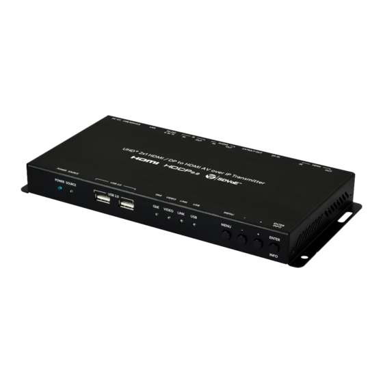
6. OPERATION CONTROLS AND FUNCTIONS 6.1 Front Panel POWER SOURCE USB 2.0 VIDEO LINK LINK MENU ENTER INFO POWER LED: This LED will illuminate to indicate the unit is on and receiving power. SOURCE LED: The illumination of this LED indicates which AV input is currently selected to be the source transmitted as an AV over IP stream. -
Page 10: Rear Panel
+ (PLUS) Button: Press to move up or adjust selections within OSD menus. When not in a menu, press to toggle the input source for the HDMI output. ENTER/INFO Button: When inside an OSD menu, press to confirm a selection or to go deeper into a menu item. When not in a menu, press to activate the Information OSD. - Page 11 IR PORTS: „ OUT Port: Connect to an IR Blaster to broadcast IR signals from a connected receiver to devices within direct line-of sight of the IR Blaster. „ IN Port: Connect to an IR Extender to receive IR control signals and extend them to devices connected to a connected receiver.
-
Page 12: Ir Cable Pinouts
6.3 IR Cable Pinouts IR Blaster IR Extender Cable Cable Power Infrared Infrared Power Not Used Ground 6.4 RS-232 Pinout and Defaults Serial Port Default Settings Baud Rate 57600 Data Bits Parity Bits None Stop Bits Flow Control None 3-pin Terminal Block Note: The default Serial Port baud rate can only be changed by use of the optional IP Master Controller or control software. -
Page 13: Osd Menu
6.5 OSD Menu All functions of this unit can be controlled by using the OSD (On Screen Display) which is activated by pressing the MENU button on the front of the unit. Use the + (PLUS), − (MINUS), and ENTER buttons to navigate the OSD menu. - Page 14 2ND LEVEL 3RD LEVEL Display Information Information Timeout 10~40 Sec (10 Sec) Menu Timeout 10~40 Sec (10 Sec) Menu H Position 0~100 (10) 0~100 (10) Menu V Position 1) Display Information: Enable or disable the Information OSD. 2) Information Timeout: Set the display timeout for the Information OSD. 3) Menu Timeout: Set the display timeout for the OSD Menu.
- Page 15 EDID 2ND LEVEL 3RD LEVEL INTERNAL 1 (FHD 2CH) HDMI EDID Internal 2 (FHD MCh) Internal 3 (UHD 2Ch) Internal 4 (UHD MCh) Internal 5 (UHD+ 2Ch) Internal 6 (UHD+ MCh) External A [HDMI Out] External B [VoIP Out] DP EDID INTERNAL 1 (FHD 2CH) Internal 2 (FHD MCh) Internal 3 (UHD 2Ch)
- Page 16 This unit provides the following 6 default EDIDs: Unit’s default EDIDs FHD 2CH 1920×1080p@60Hz (4.95Gbps), 8-bit color, LPCM 2.0 FHD MCH 1920×1080p@60Hz (4.95Gbps), 8-bit color, LPCM 7.1 & Bitstream UHD 2CH 3840×2160p@30Hz (10.2Gbps), 12-bit Deep Color, LPCM 2.0 UHD MCH 3840×2160p@30Hz (10.2Gbps), 12-bit Deep Color, LPCM 7.1 &...
- Page 17 HDCP 2ND LEVEL 3RD LEVEL HDMI HDCP Disable Follow out Follow in FOLLOW API DP HDCP Disable Follow out Follow in FOLLOW API 1) HDMI HDCP: Selects the HDCP logic to use with the HDMI input. „ Follow In: The input supports up to the HDCP version required by the connected source.
- Page 18 DEVICE SETTING 2ND LEVEL 3RD LEVEL USB Control Mode Host DEVICE USB Virtual Hub (USB Device Mode only) HDMI Out Source INPUT 1 (HDMI) Input 2 (DP) VoIP Out Source INPUT 1 (HDMI) Input 2 (DP) HDMI Out Auto Mode AUTO SWITCH VoIP Out Auto Mode AUTO SWITCH...
- Page 19 6) VOIP Out Auto Mode: Enable or disable the AVoIP streaming output’s automatic source selection mode. When enabled, the unit will automatically switch the input routed to the AVoIP output whenever a new source is detected or if the current source is lost. INFORMATION 2ND LEVEL 3RD LEVEL...
-
Page 20: Basic Av Extension
6.6 Basic AV Extension 6.6.1 Point-to-Point (One Way) The most basic extension configuration available is a point-to-point system with a single transmitter connected directly to a single receiver. In this configuration the HDMI/DP input on the transmitter side is transmitted to the connected receiver side without modification to the audio or video format. -
Page 21: Advanced Av Extension
6.7 Advanced AV Extension 6.7.1 IP Master Controller The IP Master Controller is a hardware solution designed to provide a unified and easy method to access and control all of the transmitters and receivers in a system. It provides a user-friendly, and operating system agnostic, web- based interface allowing easy control over all of the most critical functions within a distribution system. -
Page 22: Configuration Examples
6.7.2 Configuration Examples When combined with the IP Master Controller, and a 10 Gigabit Ethernet switch, this extension system gains a large number of additional configuration options including: multi-in/multi-out matrix switching with breakaway audio, video wall creation, and a multiview output mode. Audio extraction and embedding is fully controllable. - Page 23 (3) Multiview (PiP/PoP/Quad/Etc.) Configuration 10Gb Network Switch (4) KVM Switch Configuration 10Gb Network Switch...
-
Page 24: Connection Diagram
7. CONNECTION DIAGRAM Media Player 1.5m Stereo HDMI Input 60° Input IR Input & Input Output RS-232 60° Router HDMI Output Local Monitor Power HDMI AUDIO TX RX DC 12V Supply DP IN CAT6A/7 OUT RS-232 USB/SERVICE Cat6A POWER USB 2.0 VIDEO LINK LINK... -
Page 25: Specifications
8. SPECIFICATIONS 8.1 Technical Specifications HDMI Bandwidth 18Gbps DisplayPort Bandwidth 21.6Gbps CAT6A/7 Bandwidth 10Gbps Input Ports 1×HDMI (Type-A) 1×DisplayPort 1×Stereo Audio (3.5mm) Output Ports 1×10GbE LAN (RJ-45) 1×HDMI (Type-A) 1×Stereo Audio (3.5mm) Pass-through Ports 1×IR Extender (3.5mm) 1×IR Blaster (3.5mm) 1×RS-232 (3-pin Terminal Block) 2×USB (Type-A) 1×LAN (RJ-45) -
Page 26: Video Specifications
8.2 Video Specifications Input Output Supported Resolutions (Hz) HDMI HDMI 10GbE 720×400p@70/85 640×480p@60/72/75/85 720×480i@60 720×480p@60 720×576i@50 720×576p@50 ... - Page 27 Input Output Supported Resolutions (Hz) HDMI HDMI 10GbE 2560×1440p@60RB 2560×1600p@60RB 2048×1080p@24/25/30 2048×1080p@50/60 3840×2160p@24/25/30 3840×2160p@50/60 (4:2:0) 3840×2160p@24, HDR10 ...
-
Page 28: Audio Specifications
8.3 Audio Specifications 8.3.1 Digital Audio HDMI Input / Output LPCM Max Channels 8 Channels Sampling Rate (kHz) 32, 44.1, 48 Bitstream Supported Formats Standard & High-Definition DisplayPort Input LPCM Max Channels 8 Channels Sampling Rate (kHz) 32, 44.1, 48 Bitstream Supported Formats Standard &... -
Page 29: Analog Audio
8.3.2 Analog Audio Analog Input Max Audio Level 2Vrms Impedance 10kΩ Type Unbalanced Analog Output Max Audio Level 2Vrms THD+N < −80dB@0dBFS 1kHz (A-wt) > 80dB@0dBFS Frequency Response < ±1dB@20Hz~20kHz Crosstalk < −80dB@10kHz Impedance 470Ω Type Unbalanced... -
Page 30: Cable Specifications
8.4 Cable Specifications 1080p 4K30 4K60 (4:4:4) (4:4:4) Cable Length 8-bit 12-bit 8-bit 8-bit High Speed HDMI Cable HDMI Input HDMI Output DisplayPort Cable DisplayPort Input Ethernet Cable Cat.6A/7 100m Bandwidth Category Examples: • 1080p (FHD Video) - Up to 1080p@60Hz, 12-bit color - Data rates lower than 5.3Gbps or below 225MHz TMDS clock •... -
Page 31: Acronyms
9. ACRONYMS ACRONYM COMPLETE TERM 10GbE 10 Gigabit Ethernet Analog-to-Digital Converter AVoIP Audio/Video over IP Cat.5e Enhanced Category 5 cable Cat.6 Category 6 cable Cat.6A Augmented Category 6 cable Cat.7 Category 7 cable Digital-to-Analog Converter Decibel DHCP Dynamic Host Configuration Protocol DisplayPort Digital Visual Interface EDID... - Page 32 ACRONYM COMPLETE TERM LPCM Linear Pulse-Code Modulation Media Access Control Megahertz On-Screen Display Picture in Picture Picture outside of Picture SDVoE Software Defined Video over Ethernet Signal-to-Noise Ratio Transmission Control Protocol THD+N Total Harmonic Distortion plus Noise TMDS Transition-Minimized Differential Signaling 4K UHD 4K Ultra-High-Definition (10.2Gbps max) 4K UHD...
- Page 36 CYPRESS TECHNOLOGY CO., LTD. www.cypress.com.tw...
Need help?
Do you have a question about the AVIP-P5104T-B1C and is the answer not in the manual?
Questions and answers