
Subscribe to Our Youtube Channel
Related Manuals for CYP CDPS-P313RTX


Summary of Contents for CYP CDPS-P313RTX
- Page 1 CDPS-P313RTX 4×1 Multi-input to HDBT Live Video Streaming Transmitter with Recording Operation Manual Operation Manual...
- Page 3 DISCLAIMERS The information in this manual has been carefully checked and is believed to be accurate. Cypress Technology assumes no responsibility for any infringements of patents or other rights of third parties which may result from its use. Cypress Technology assumes no responsibility for any inaccuracies that may be contained in this document.
- Page 4 SAFETY PRECAUTIONS Please read all instructions before attempting to unpack, install or operate this equipment and before connecting the power supply. Please keep the following in mind as you unpack and install this equipment: • Always follow basic safety precautions to reduce the risk of fire, electrical shock and injury to persons.
-
Page 5: Table Of Contents
CONTENTS 1. Introduction ............1 2. Applications ............. 1 3. Package Contents ........... 2 4. System Requirements ........2 5. Features............3 6. Operation Controls and Functions ....4 6.1 Front Panel ..........4 6.2 Rear Panel........... 6 6.3 IR Cable Pinouts.......... 7 6.4 RS-232 Pinout and Defaults ...... - Page 6 8.3 Audio Specifications ........45 8.3.1 Digital Audio ........45 8.3.2 Analog Audio ........45 8.4 Cable Specifications ........46 8.5 HDBaseT Features ........47 9. Acronyms ............48...
-
Page 7: Introduction
1. INTRODUCTION This Video Streaming Transmitter with Recording makes online broadcasting of live video, with a locally stored archive, an easy and simple process. Video sources from cameras, PCs, video game consoles, etc. are a breeze to connect for immediate broadcast and recording. Video content up to 4K UHD (4K@60Hz, 4:2:0, 8-bit) is supported and is automatically scaled to a resolution that is more appropriate for efficient streaming. -
Page 8: Package Contents
3. PACKAGE CONTENTS • 1× 4×1 Multi-input to HDBT Live Video Streaming Transmitter with Recording • 1× 24V/3.75A DC Power Adapter • 1× AC Power Cord • 2× 5-pin Terminal Block • 2× 4-pin Terminal Block • 1× IR Blaster Cable •... -
Page 9: Features
5. FEATURES • 4 inputs (HDMI, DisplayPort, USB-C, and VGA) • 1 HDBaseT output • Digital inputs are HDCP 1.x and HDCP 2.2 compliant Note: HDCP encrypted sources cannot be streamed over the Internet or recorded and will be blacked out •... -
Page 10: Operation Controls And Functions
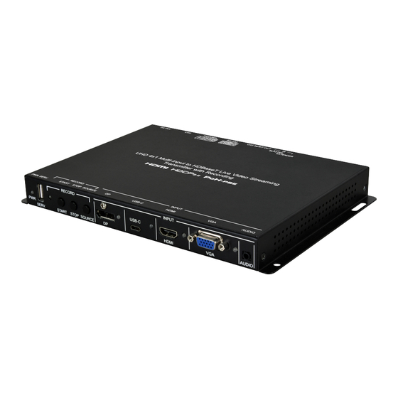
6. OPERATION CONTROLS AND FUNCTIONS 6.1 Front Panel RECORD INPUT USB-C PWR. SERV. START STOP SOURCE HDMI AUDIO PWR. LED: This LED will illuminate to indicate the unit is on and receiving power. SERV. Port: Attach a standard USB thumb drive or external hard drive for storage of recorded video. - Page 11 VGA INPUT Port & LED: Connect to VGA source equipment such as a PC or laptop. The LED will illuminate amber when a source is detected and green when the source is selected. AUDIO INPUT Port: Connect to the stereo analog output of the device connected to the VGA input port.
-
Page 12: Rear Panel
6.2 Rear Panel EXTENDER BYPASS BLASTER CAT 5e/6/7 OUT RS-232 TRIGGER DC 24V IR EXTENDER Port: Connect to an IR Extender to receive IR control signals and extend them to devices connected to the other end of the HDBaseT connection. Ensure that the remote being used is within direct line-of-sight of the IR Extender. -
Page 13: Ir Cable Pinouts
6.3 IR Cable Pinouts IR Blaster IR Extender Cable Cable Power Infrared Infrared Power Not Used Ground 6.4 RS-232 Pinout and Defaults Serial Port Default Settings (Unit Control) Baud Rate 19200 Data Bits Parity Bits None Stop Bits Flow Control None RS-232 Port 1 (Unit Control) RS-232 Port 2 (Bypass) -
Page 14: Webgui Control
6.5 WebGUI Control • Device Discovery Please obtain the “Device Discovery” software from your authorized dealer and save it in a directory where you can easily find it. Connect the unit and your PC/Laptop to the same active network and execute the “Device Discovery”... - Page 15 • WebGUI Overview After connecting to the WebGUI’s address in a web browser, the login screen will appear. Please enter the appropriate user name and password then click “Submit” to log in. Note: The default user name and password is “admin”. On the left side of the browser you will see the following menu tabs where all primary functions of the unit are controllable via the built in WebGUI.
-
Page 16: Live Tab
6.5.1 Live Tab This tab provides viewing access to the first local video stream channel (of 4 channels total) generated by the unit. The video source can be selected here and the stream resolution, framerate and bitrate is also displayed. At the bottom of the page, a connection address for local video stream channel 1 is displayed in the format: “rtsp://xxx.xxx.xxx.xxx/live/ch1/h264_aac”... -
Page 17: Video Switch Tab
6) Video Window: This video window displays the content of streaming channel 1 and provides the details of a direct connection address that can be used to connect to this stream using 3rd party video player software such as VLC or PotPlayer. Note: Video streaming preview support within the WebGUI requires the use of the Chrome, Internet Explorer or Safari browser with the appropriate plugins (VLC for IE and Safari or VXG Player for Chrome) - Page 18 ■ Output: Click on this button to begin routing selection as detailed above. Click the Edit icon ( ) to open the Output Edit window and modify additional output settings. ■ Input: Rename the input or view the current HDCP behavior (Digital inputs only) by clicking on the Edit icon ( ) to open the editing window.
-
Page 19: Edid Setting Tab
6.5.3 EDID Setting Tab This tab provides the option of four standard EDIDs, one sink sourced EDID and four customer uploaded EDIDs that can be assigned to the digital input ports. The names of the four customer uploaded EDIDs can changed if desired. - Page 20 3) Set EDID Input Content: Click on the switch select how to assign EDIDs to the unit’s inputs (Appoint/All). Selecting “Appoint” allows for a different EDID to be assigned to each input, selecting “All” allows for a single EDID to be assigned to all inputs. After making the mode selection, click on the input button to open the EDID Source selection window.
-
Page 21: Record Setting Tab
6.5.4 Record Setting Tab This tab provides access to the settings and controls for configuring the channel 1 stream (the same stream viewed on the “Live” tab) and making a recording of it to a local or network storage location. When recording is enabled, the channel 1 video stream is saved as a *.mp4 file, encoded with the H.264 codec, to one of three possible target destinations: USB storage, network storage using NFS, or network storage using CIFS. - Page 22 2) Storage: Use the drop-down to select the storage target to use when recording. Available choices are: Auto, USB (USB storage), NFS (NFS based network storage), and CIFS (CIFS based network storage). Selecting “Auto” will use the first available valid storage location using the following priority order: NFS >...
- Page 23 8) Remote Storage (NAS) CIFS: This section provides a way to configure access to a NAS (Network Attached Storage) device using the CIFS protocol. ■ Enable: Enable or disable access to the defined CIFS based network storage server. ■ Remote IP: Enter the IP address of the target CIFS based NAS device.
-
Page 24: Time Setting Tab
6.5.5 Time Setting Tab The Time Settings tab provides a way to set the system’s time, date, and time zone. The system time can be set manually, or automatically using a defined SNTP server. If your country uses DST (Daylight Saving Time) you can enable or disable it here and configure the start and end times/dates so that your scheduled events will always occur at the correct times throughout the year. - Page 25 2) Time Configuration ■ Date & Time: The unit’s time and date can be manually configured here if an internet connection, or NTP server is not available. Click on the calendar icon ( ) to open the time and date configuration screen and select the preferred values.
-
Page 26: Trigger Setting Tab
6.5.6 Trigger Setting Tab This tab allows user to define the action taken when any of the 8 trigger pins within the Trigger Terminal Block are activated. 1) Set Trigger Input: Use the dropdown next to each Trigger (1~8) to assign an action to perform when that trigger is activated. -
Page 27: User Config Tab
6.5.7 User Config Tab The WebGUI and Telnet username/password are set on this page. Two management levels are available: “Administrator” and “General User”. The administrator username (“admin”) cannot be changed. The “Administrator” user has access to all tabs and can change all settings. The “General User”... - Page 28 1) Network: IP mode may be switched between Static IP or DHCP. In Static IP mode the IP, netmask and gateway addresses may be manually set. When in DHCP mode, the unit will attempt to connect to a local DHCP server and obtain IP, netmask and gateway addresses automatically.
-
Page 29: Telnet Control
6.6 Telnet Control Before attempting to use Telnet control, please ensure that both the unit and the PC are connected to the same active networks. To Access the Command Line Interface (CLI) Windows 7 Click Start, type “cmd” in the search field, and press Enter. -
Page 30: Serial And Telnet Commands
6.7 Serial and Telnet Commands COMMAND Description and Parameters help Show the full command list. ? Show the full command list. set factory default Reset the unit to the factory defaults. set factory ipconfig default Reset the unit’s network settings to the factory defaults. set factory out route default... - Page 31 COMMAND Description and Parameters get model name Show the unit's model name. get model type Show the unit's product type. get user config List the unit's current configuration information. get all command index list Show the unit’s full console command index list. set uart 1 reset...
- Page 32 COMMAND Description and Parameters get ipconfig Show the unit's current IP configuration information set ip addr N1 Set the unit's static IP address. N1 = X.X.X.X [X = 0~255] get ip addr Show the unit's current IP address. set netmask N1 Set the unit's static netmask.
- Page 33 COMMAND Description and Parameters set webgui login timeout N1 Set the WebGUI inactivity timeout value. Available values for N1: [No timeout] 1~60 [Timeout in minutes] get webgui login timeout Show the current WebGUI inactivity timeout value. set in N1 name N2 Set the name of the specified input.
- Page 34 COMMAND Description and Parameters get out name list List the names of all outputs on the unit. set out auto mode N1 Set the auto switching behavior of the unit. Available values for N1: [Disabled] [Auto switch] get out auto mode Show the current auto switching mode of the unit.
- Page 35 COMMAND Description and Parameters get in N1 refresh rate Show the refresh rate of the specified input's current video source. Available values for N1: [DisplayPort input] [USB-C input] [HDMI input] [VGA input] get in N1 interlace Show the interlace state of the specified input's current video source. Available values for N1: [DisplayPort input] [USB-C input]...
- Page 36 COMMAND Description and Parameters get in N1 uni timing Show the index number of the current resolution detected on the speci- fied input. (Universal index number) Available values for N1: [DisplayPort input] [USB-C input] [HDMI input] [VGA input] get in N1 type list List the port type of all inputs on the unit.
- Page 37 COMMAND Description and Parameters get out A sync status Show the current sync state of the specified output. get out timing list List all available output resolutions with their local index numbers. get out uni timing list List all available output resolutions with their universal timing index numbers.
- Page 38 COMMAND Description and Parameters get out A osd Show the current OSD banner state. set out A osd banner location N1 Set the OSD banner location. Available values for N1: [Left top] [Center top] [Right top] get out A osd banner location Show the current OSD banner location.
- Page 39 COMMAND Description and Parameters get out banner font color list List all available font colors for the OSD banner. set out A banner font transparency level N1 Set the text transparency level for the OSD banner. N1 = 1~8 [Transparency level] get out A banner font transparency level...
- Page 40 COMMAND Description and Parameters get all in edid list List the EDIDs assigned to all inputs. get internal N1 edid data Show the specified Internal EDID as hex data. Available values for N1: [FHD 2CH] [FHD MCH] [4K UHD 2CH] [4K UHD MCH] set all in edid mode N1...
- Page 41 COMMAND Description and Parameters get sink A edid info Show English readable details from the EDID of the display connected to the output. set in N1 edid N2 Set the EDID to use on the specified input. Available values for N1: [DisplayPort input] [USB-C input] [HDMI input]...
- Page 42 COMMAND Description and Parameters set edid N1 name N2 Set the name for the specified EDID. Available values for N1: [User EDID 1] [User EDID 2] [User EDID 3] [User EDID 4] N2 = {Name} [16 characters max] Note: Only User EDIDs may be renamed. get edid N1 name...
- Page 43 COMMAND Description and Parameters get record mode Show the current recording state. set record overwrite N1 Enable or disable record overwrite support. Available values for N1: [Enable overwriting] [Disable overwriting] get record overwrite Show the current state of record overwrite support. set record media path N1...
- Page 44 COMMAND Description and Parameters set record resolution N1 Set the resolution to use when recording (streaming channel 1). Available values for N1: 320x240 [QVGA] 640x480 [VGA] 1920x720 [720p] 1920x1080 [1080p] get record resolution Show the resolution used when recording (streaming channel 1). set record bitrate N1...
-
Page 45: Connection Diagram
7. CONNECTION DIAGRAM Compatible RX with connected display PC/Laptop 60° Macro Macro Trigger Control Macro Macro Keypad Macro Macro Cat.5e/6/7 Trigger Macro Macro Cable 1.5m Input 60° Router IR Input & Output EXTENDER BYPASS BLASTER CAT 5e/6/7 OUT RS-232 TRIGGER DC 24V INPUT RECORD... -
Page 46: Specifications
8. SPECIFICATIONS 8.1 Technical Specifications HDMI Bandwidth 10.2Gbps DisplayPort Bandwidth 10.2Gbps USB-C Bandwidth 10.2Gbps VGA Bandwidth 165MHz HDBaseT Bandwidth 10.2Gbps Input Ports 1×HDMI (Type-A) 1×DisplayPort 1×USB (Type-C) 1×VGA (HD-15) 1×Analog Stereo (3.5mm) Output Port 1×HDbaseT (RJ-45) Control/Streaming Port 1×LAN (RJ-45) Pass-through Ports 1×IR Extender (3.5mm) 1×IR Blaster (3.5mm) -
Page 47: Video Specifications
Operating Temperature 0˚C – 40˚C/32˚F – 104˚F Storage Temperature -20˚C – 60˚C/-4˚F – 140˚F Relative Humidity 20 – 90% RH (Non-condensing) Power Consumption 39.84W 8.2 Video Specifications 8.2.1 Video Inputs Input Supported Resolutions (Hz) HDMI USB-C 320×240@25/30/50/60 ... - Page 48 Input Supported Resolutions (Hz) HDMI USB-C 1400×1050p@60 1440×900p@60/75 1600×900p@60RB 1600×1200p@60 1680×1050p@60 1920×1080i@50/60 1920×1080p@24/25/30 1920×1080p@50/60 ...
-
Page 49: Video Outputs
8.2.2 Video Outputs Output Supported Resolutions (Hz) HDBaseT H.264 Stream 320×240@25/30/50/60 720×400p@70/85 640×480p@25/30/50 640×480p@60/72/75/85 720×480i@60 720×480p@60 720×576i@50 720×576p@50 800×600p@56/60/72/75/85 848×480p@60 1024×768p@60/70/75/85 1152×864p@75 ... - Page 50 Output Supported Resolutions (Hz) HDBaseT H.264 Stream 1920×1080p@50/60 1920×1200p@60RB 2560×1440p@60RB 2560×1600p@60RB 2048×1080p@24/25/30 2048×1080p@50/60 3840×2160p@24/25/30 3840×2160p@50/60 (4:2:0) 3840×2160p@24, HDR10 3840×2160p@50/60 (4:2:0), HDR10 ...
-
Page 51: Audio Specifications
8.3 Audio Specifications 8.3.1 Digital Audio HDMI, DisplayPort, USB-C Input / HDBaseT Output LPCM Max Channels 8 Channels Sampling Rate (kHz) 32, 44.1, 48, 88.2, 96, 176.4, 192 Bitstream (HDBaseT bypass only) Supported Formats Standard & High-Definition Streaming Output LPCM Max Channels 2 Channels Sampling Rate (kHz) -
Page 52: Cable Specifications
8.4 Cable Specifications 1080p 4K30 4K60 (4:4:4) (4:4:4) 8-bit 12-bit 8-bit 8-bit Cable Length High Speed HDMI Cable HDMI Input DisplayPort Cable DisplayPort Input USB-C Cable USB-C Input VGA Cable VGA Input Ethernet Cable Cat.5e/6 Cat.6A/7 ... -
Page 53: Hdbaset Features
8.5 HDBaseT Features HDBaseT Feature Set Transmitter Video & Audio Extension Supported LAN Extension Unsupported Send power to Receiver Supported (PoH) Accept power from Receiver Unsupported IR Extension Supported RS-232 Extension Supported USB 2.0 Extension Unsupported... -
Page 54: Acronyms
9. ACRONYMS ACRONYM COMPLETE TERM Analog-to-Digital Converter ASCII American Standard Code for Information Interchange Cat.5e Enhanced Category 5 cable Cat.6 Category 6 cable Cat.6A Augmented Category 6 cable Cat.7 Category 7 cable Command-Line Interface Decibel DHCP Dynamic Host Configuration Protocol DisplayPort Digital Visual Interface EDID... - Page 55 ACRONYM COMPLETE TERM Powered Device Power over HDBaseT Power Sourcing Equipment Signal-to-Noise Ratio Transmission Control Protocol THD+N Total Harmonic Distortion plus Noise 4K UHD 4K Ultra-High-Definition (10.2Gbps max) 4K UHD 4K Ultra-High-Definition (18Gbps max) Universal Serial Bus Video Graphics Array WUXGA (RB) Widescreen Ultra Extended Graphics Array (Reduced Blanking)
- Page 56 CYPRESS TECHNOLOGY CO., LTD. www.cypress.com.tw...
Need help?
Do you have a question about the CDPS-P313RTX and is the answer not in the manual?
Questions and answers