
Related Manuals for CYP CH-U331TX


Summary of Contents for CYP CH-U331TX
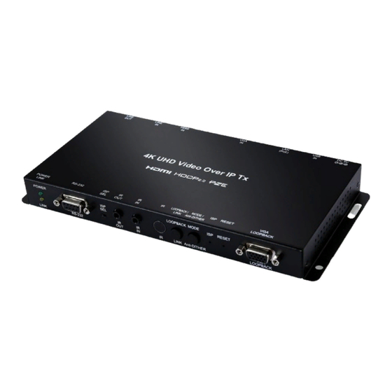
- Page 1 CH-U331TX HDMI/VGA over IP Transmitter with USB/KVM Extension Operation Manual Operation Manual...
- Page 2 DISCLAIMERS The information in this manual has been carefully checked and is believed to be accurate. Cypress Technology assumes no responsibility for any infringements of patents or other rights of third parties which may result from its use. Cypress Technology assumes no responsibility for any inaccuracies that may be contained in this document.
- Page 3 SAFETY PRECAUTIONS Please read all instructions before attempting to unpack, install or operate this equipment and before connecting the power supply. Please keep the following in mind as you unpack and install this equipment: • Always follow basic safety precautions to reduce the risk of fire, electrical shock and injury to persons.
-
Page 4: Table Of Contents
CONTENTS 1. Introduction ............1 2. Applications .............1 3. Package Contents ..........2 4. System Requirements ........2 5. Features ............3 6. Operation Controls and Functions ....4 6.1 Transmitter's Front Panel ......4 6.2 Transmitter's Rear Panel ......6 6.3 IR Cable Pin Assignments ......7 6.4 RS-232 Protocol .......... -
Page 5: Introduction
1. INTRODUCTION This unit is part of a 4K UHD Multi-Function Extension system that allows you to extend HDMI or VGA signals along with KVM using the TCP/ IP protocol over regular Cat.5e/6/7 network cable. This extender supports the transmission of Ultra High-Definition signals (up to 4K@30Hz YUV 4:4:4 or 4K@60Hz YUV 4:2:0) with audio and USB up to 100m on a single cable. -
Page 6: Package Contents
3. PACKAGE CONTENTS • 1×HDMI/VGA over IP Transmitter with USB/KVM Extension • 1×IR Extender Cable • 1×IR Blaster Cable • 1×5V/2.6A DC Power Adaptor • 1×Operation Manual 4. SYSTEM REQUIREMENTS • HDMI or VGA source equipment such as media players, video game consoles, PCs or set-top boxes. -
Page 7: Features
5. FEATURES • HDMI 2.0 and DVI 1.0 compliant • HDCP 1.4 & 2.2 compliant • 1×HDMI input, 1×VGA input & 1×VGA bypass output • Video, audio and control transmission over TCP/IP in Unicast (point- to-point) or Multicast (single-to-many) modes •... -
Page 8: Operation Controls And Functions
6. OPERATION CONTROLS AND FUNCTIONS 6.1 Transmitter's Front Panel POWER LOOPBACK MODE RESET RS-232 LINK LINK Anti-DITHER LOOPBACK 7 8 9 1011 POWER LED: This LED will flash while the unit is powering on and will illuminate solidly once it is ready to be used. LINK LED: If the Transmitter has no network connection the LINK LED will not illuminate. - Page 9 Note: When the Transmitter is in multicast mode the IR signal is sent to all associated Receivers. LOOPBACK/LINK: This button controls multiple functions: Loopback: Press this button momentarily to toggle the VGA Loopback function on and off, allowing you to locally monitor non- HDCP HDMI sources (1080p or below) for troubleshooting purposes.
-
Page 10: Transmitter's Rear Panel
lower) source. 6.2 Transmitter's Rear Panel DC 5V LAN (PoE) VGA IN HDMI IN LINE IN LINE OUT DC 5V: Plug the 5V DC power adapter into the unit and connect it to an AC wall outlet for power. (Optional if powered by PoE) USB: Connect directly to a PC to extend its USB functionality to the ports on the connected Receiver. -
Page 11: Ir Cable Pin Assignments
6.3 IR Cable Pin Assignments IR Extender IR Signal Power Ground IR Blaster Power IR Signal 6.4 RS-232 Protocol TRANSMITTER RECEIVER Definition Definition ► ◄... -
Page 12: Telnet Commands
6.5 Telnet Commands 1. Help COMMAND DESCRIPTION AND PARAMETERS HELP Show the full command list. HELP N1 Show help details about command N1 = {Any command name} 2. Network COMMAND DESCRIPTION AND PARAMETERS GET_IPCONFIG Show the current IP configuration. SET_IP_MODE N1 Set the IP configuration mode. - Page 13 2. Network COMMAND DESCRIPTION AND PARAMETERS SET_JUMBO_MTU N1 Enable/disable the jumbo frame MTU. Available values for N1: [Disabled] [Enabled] GET_JUMBO_MTU Show the jumbo frame MTU state. 3. System COMMAND DESCRIPTION AND PARAMETERS GET_HARDWARE_VERSION Show the current hardware version. FACTORY_RESET N1 Perform a factory reset on the unit and select the IP mode after the reset completes.
- Page 14 4. Transmitter Specific COMMAND DESCRIPTION AND PARAMETERS SET_HDCP_ALLOW N1 Enable/disable HDCP encrypted source support. Available values for N1: [Disabled] [Enabled] GET_HDCP Show the current HDCP support state. SET_USB_MOUSE N1 Set the USB mouse performance mode. Available values for N1: [High resolution mode] [Compatibility mode] GET_USB_MOUSE Show the current USB mouse...
- Page 15 4. Transmitter Specific COMMAND DESCRIPTION AND PARAMETERS Note: Target Receiver number can be obtained by turning on the Video Wall OSD. Omitting N2 makes the setting global to all Receivers. SET_VW_LAYOUT N1 N2 {N3} Set the video wall’s total horizontal and vertical display count.
- Page 16 4. Transmitter Specific COMMAND DESCRIPTION AND PARAMETERS SET_VW_BC N1 N2 N3 N4 {N5} Set the video wall display’s bezel compensation values. N1 = 0~99999 [Video width] N2 = 0~99999 [Total display width] N3 = 0~99999 [Video height] N4 = 0~99999 [Total display height] N5 = 0~255 [Target Rx {Optional}] Note: Target Receiver number can...
- Page 17 4. Transmitter Specific COMMAND DESCRIPTION AND PARAMETERS SET_VW_SHIFT N1 N2 {N3} Set the video wall display’s output shift. Available values for N1: [Shift up] [Shift down] [Shift left] [Shift right] N2 = 0~80000 [Pixel shift amount. Must be in increments of 8.] N3 = 0~255 [Target Rx {Optional}]...
- Page 18 5. Receiver Specific COMMAND DESCRIPTION AND PARAMETERS R N1 Select the VoIP transmission channel to display. N1 = 0~255 GET_RX_CHANNEL Show the currently selected VoIP transmission channel. SET_OUTPUT_RES N1 Set the output resolution. Available values for N1: [640×480@60Hz] [800×600@60Hz] [1024×768@60Hz] [1280×768@60Hz] [1280×800@60Hz] [1280×1024@60Hz]...
- Page 19 5. Receiver Specific COMMAND DESCRIPTION AND PARAMETERS SET_OUTPUT_RES N1 [1080p@25Hz] [1080p@24Hz] Note: Downscaling is limited to 1/2 of the horizontal/vertical pixels of the source. For example: 3840×2160 (4K) to 1920×1080 (1080p) is OK, but 3840×2160 (4K) to 1280×720 (720p) or 640×480 is not.
- Page 20 5. Receiver Specific COMMAND DESCRIPTION AND PARAMETERS SET_VW_POS N1 N2 Set the position within the video wall of the display connected to this Receiver. (Cannot exceed the video wall’s horizontal and vertical display count.) N1 = 0~15 [Row] N2 = 0~15 [Column] GET_VW_POS Show the position within the video...
- Page 21 5. Receiver Specific COMMAND DESCRIPTION AND PARAMETERS GET_VW_VSCALE Show the vertical zoom amount of the display connected to this receiver. SET_VW_SHIFT N1 N2 Set the video output shift of the display connected to this receiver. Available values for N1: [Shift up] [Shift down] [Shift left] [Shift right]...
- Page 22 6. Serial COMMAND DESCRIPTION AND PARAMETERS SET_SERIAL_BAUD N1 Set the Serial baud rate. Available values for N1: [300] [600] [1200] [2400] [4800] [9600] [19200] [38400] [57600] [115200] GET_SERIAL_BAUD Show the current Serial baud rate. SET_SERIAL_BITS N1 Set the number of Serial data bits. Available values for N1: [5 bits] [6 bits]...
- Page 23 7. USB COMMAND DESCRIPTION AND PARAMETERS SET_USB_ALLOW N1 Enable/disable USB support. Available values for N1: [Disabled] [Enabled] GET_USB_ALLOW Show current USB support state. 8. Video COMMAND DESCRIPTION AND PARAMETERS VIDEO_SOURCE_HDMI Select HDMI as the video input source. VIDEO_SOURCE_VGA Select VGA as the video input source.
-
Page 24: Webgui Control
6.6 WebGUI Control • Important Notes - All major functions of the unit, including status, streaming method, streaming channel selection, output resolution, video wall configuration, EDID management, Ethernet settings, and reset/firmware functions are controllable via multiple tabs in the WebGUI interface allowing for reasonably intuitive operation. - Each Transmitter and Receiver is controlled by its own WebGUI interface which may be accessed by opening a standard web browser on a PC and typing in the IP address of the unit you wish... -
Page 25: System Tab
switch with jumbo frame support and IGMP snooping is required. A professional managed switch with VLAN support is strongly recommended. Please note that most consumer-grade routers are not able to handle the high traffic rates generated by multicast mode, so using a router directly as your network switch is discouraged. - Page 26 • Utilities The Utilities window allows users to reset the unit back to the factory defaults by clicking “Factory Default". The unit may be rebooted (without resetting settings) by pressing the “Reboot” button. If the EDID received from the primary Receiver unit (selected via a checkbox on the preferred Receiver in Multicast mode) has compatibility issues with the connected HDMI source, the internal HDMI EDID (up to 4K30 w/audio) or VGA EDID (up to WUXGA wo/...
- Page 27 • Statistics The Statistics window shows all available information about the operational status of the unit, including current Host ID Name, Ethernet information, MAC address, unicast/multicast mode, link status and mode.
-
Page 28: Video Wall Tab
6.6.2 Video Wall Tab The Video Wall tab allows user to design, edit and manipulate a video wall system created using multiple Receiver units connected to identical displays. The bezel and video size of the displays being used, as well as the horizontal and vertical monitor count, is defined here. - Page 29 • Bezel and Gap Compensation This section of the Video Wall tab is used to define the physical dimensions of each display being used in the video wall. Accurate measurements are needed of the monitor’s outer frame (OW, OH) and the video screen (VW, VH). The measurements may be made using any unit of measurement (inches, mm, cm, etc.) as long as ALL measurements in the same wall are made using the exact same units and the numbers are integers.
- Page 30 - VW (Video Width): This is the horizontal measurement of the display’s video screen. - VH (Video Height): This is the vertical measurement of the display’s video screen. Note: Typically all monitors in a video wall are identical and have the same dimensions, but it is possible to use differently sized displays as long as the same measurement units are used to measure each display and the displays are still arranged in a normal rectangular...
- Page 31 - Stretch Type: Set the video stretch method. - Selecting “Fit In” will expand the video to exactly fit the dimensions of the video wall regardless of the source’s original aspect ratio. - Selecting “Stretch Out” will zoom the video until the video wall is filled in all 4 dimensions while maintaining the aspect ratio of the original source.
-
Page 32: Network Tab
6.6.3 Network Tab The Network tab provides controls over the Transmitter’s broadcast channel, IP configuration, and network broadcast mode. Changes made to the network settings will require a reboot of the unit. After clicking on “Apply” please follow the reboot instructions in the WebGUI. - Page 33 Ethernet settings of the unit. It also provides an easy way to find the physical unit when installed with many other similar units. - IP Mode & Settings: The IP mode may be switched between “Auto IP”, “DHCP” or “Static IP”. When the unit is set to Auto IP mode it will automatically assign itself an APIPA address from the 169.254.xxx.xxx range.
-
Page 34: Functions Tab
6.6.4 Functions Tab The Functions tab provides control over the Transmitter’s video source selection, streaming bandwidth/quality settings, as well as a wide variety of optional features and functions, including USB and Serial control extension. Changes made to these settings typically require a reboot of the unit. - Page 35 • Video over IP This section allows control over many critical functions of the Transmitter including: selection of the input source, enabling/ disabling the VoIP stream, enabling access to the Video Wall tab, and controlling the streaming bit rate and quality. - HDMI/VGA: Switch between the HDMI or VGA input on the Transmitter.
- Page 36 Note: If the framerate is lowered too far with motion video sources, the video will become noticeably choppy. • USB over IP This section provides controls for the USB over IP extension functionality, including enabling/disabling USB support, changing the USB operational mode, and enabling special compatibility modes.
- Page 37 • Serial over IP This section provides controls for the Serial over IP extension functionality, including enabling/disabling Serial support and setting the RS-232 data configuration. - Enable Serial over IP: Unchecking this checkbox will completely disable support for sending RS-232 commands over this stream. This option should generally remain checked, but, if serial support is not required, disabling this feature can save a very small amount of bandwidth.
-
Page 38: Connection Diagram
7. CONNECTION DIAGRAM PC/Laptop Monitor DVD/Blu-ray Player VGA & 1.5m Analog HDMI Loopback 60° Stereo Input 60° Output Inputs Powered RS-232 IR Input Speakers IR Output POWER LOOPBACK MODE RESET LINK RS-232 LINK Anti-DITHER LOOPBACK Analog DC 5V Stereo LAN (PoE) VGA IN HDMI IN LINE IN... -
Page 39: Specifications
8. SPECIFICATIONS 8.1 Technical Specifications HDMI Bandwidth 340MHz/10.2Gbps Input Ports 1×HDMI 1×VGA 1×3.5mm (Stereo Audio) 1×IR Extender [3.5mm] 1×RS-232 [9-pin D-sub] 1×USB Type-B Output Ports 1×Cat.5e/6/7 (LAN) 1×3.5mm (Stereo Audio) 1×IR Blaster [3.5mm] Supported Resolutions 480i@60Hz - 4K@30Hz (4:4:4, 8-bit) VGA@60Hz - WUXGA@60Hz (RB) IR Frequency 30 - 50kHz (30 - 60kHz under ideal... -
Page 40: Video Specifications
Relative Humidity 20 - 90% RH (Non-condensing) Power Consumption 7.15W 8.2 Video Specifications Input Output Supported Resolutions (Hz) HDMI HDMI 640×480p@60 720×480p@59/60 720×576p@50 800×600p@60 1024×768p@60 ... -
Page 41: Audio Specifications
Notes: • HDMI Input: Up to 4096×2160p@60Hz (YUV 4:2:0). • HDMI Output: HDMI input at 4K@60Hz (YUV 4:2:0) will automatically be converted to 4K@30Hz (RGB) for output. • VESA VGA up to 1920×1200@60Hz (Pixel clock<150MHz). 8.3 Audio Specifications Supported Audio Formats: Supported Formats (kHz) HDMI Input HDMI Output... - Page 42 Unicast Data Transmission Mode: Audio Inputs Audio Outputs HDMI IN LINE IN MIC IN HDMI LINE OUT LINE OUT (TX) (TX) (RX) OUT (RX) (TX) (RX) ● ● ● ■ ■ ■ ● ■ ■ ■ ▲ ■ ▲ ■ ▲...
-
Page 43: Acronyms
9. ACRONYMS ACRONYM COMPLETE TERM Cat.5e Category 5 (enhanced) Cable Cat.6 Category 6 Cable Cat.7 Category 7 Cable Digital Visual Interface EDID Extended Display Identification Data Graphical User Interface High-Definition HDCP High-bandwidth Digital Content Protection HDMI High-Definition Multimedia Interface Internet Protocol Infrared Local Area Network LPCM... - Page 44 CYPRESS TECHNOLOGY CO., LTD. www.cypress.com.tw...
- Page 45 CH-U331RX HDMI/VGA over IP Receiver with USB/KVM Extension Operation Manual Operation Manual...
- Page 46 DISCLAIMERS The information in this manual has been carefully checked and is believed to be accurate. Cypress Technology assumes no responsibility for any infringements of patents or other rights of third parties which may result from its use. Cypress Technology assumes no responsibility for any inaccuracies that may be contained in this document.
- Page 47 SAFETY PRECAUTIONS Please read all instructions before attempting to unpack, install or operate this equipment and before connecting the power supply. Please keep the following in mind as you unpack and install this equipment: • Always follow basic safety precautions to reduce the risk of fire, electrical shock and injury to persons.
- Page 48 CONTENTS 1. Introduction ............1 2. Applications .............1 3. Package Contents ..........2 4. System Requirements ........2 5. Features ............3 6. Operation Controls and Functions ....4 6.1 Receiver's Front Panel....... 4 6.2 Receiver's Rear Panel ....... 6 6.3 IR Cable Pin Assignments ......8 6.4 RS-232 Protocol ..........
-
Page 49: Introduction
1. INTRODUCTION This unit is part of a 4K UHD Multi-Function Extension system that allows you to extend HDMI or VGA signals along with KVM using the TCP/ IP protocol over regular Cat.5e/6/7 network cable. This extender supports the transmission of Ultra High-Definition signals (up to 4K@30Hz YUV 4:4:4 or 4K@60Hz YUV 4:2:0) with audio and USB up to 100m on a single cable. -
Page 50: Package Contents
3. PACKAGE CONTENTS • 1×HDMI/VGA over IP Receiver with USB/KVM Extension • 1×IR Extender Cable • 1×IR Blaster Cable • 1×5V/4A DC Power Adaptor • 1×Power Cord • 1×Operation Manual 4. SYSTEM REQUIREMENTS • HDMI or VGA source equipment such as media players, video game consoles, PCs or set-top boxes. -
Page 51: Features
5. FEATURES • HDMI 2.0 and DVI 1.0 compliant • HDCP 1.4 & 2.2 compliant • 1×HDMI output, 1×VGA output • Video, audio and control transmission over TCP/IP in Unicast (point- to-point) or Multicast (single-to-many) modes • Multi-monitor video wall support with 90° rotation •... -
Page 52: Operation Controls And Functions
6. OPERATION CONTROLS AND FUNCTIONS 6.1 Receiver's Front Panel POWER SWITCH RESET LINK USB 2.0 USB 1.1 MODE LINK RS-232 7 8 9 10 11 12 POWER LED: This LED will flash while the unit is powering on and will illuminate solidly once it is ready to be used. - Page 53 CH+/LINK: This button controls multiple functions: Channel +: Press this button momentarily to increase the streaming channel to the next available channel on the local network. Note: If no other channels are detected, the channel number will not change. Video Link: Press and hold the button for 3 seconds to enable or disable the Video Link.
-
Page 54: Receiver's Rear Panel
ISP SEL: For Factory use only. By default this is set to the left (away from the RS-232 port) and allows normal RS-232 functionality. Setting this switch to the right enables ISP engineering mode. RS-232: Connect directly to an RS-232 controllable device to receive commands from the device connected to the Transmitter. - Page 55 ISP: For factory use only. LAN 1 (PoE)~3: Connect via a Gigabit Ethernet switch to compatible Receiver(s) to transmit data, or to a PC/laptop to control the unit via WebGUI. Note: This unit can be powered directly by the connected Gigabit Ethernet switch if it provides PoE (802.3af).
-
Page 56: Ir Cable Pin Assignments
6.3 IR Cable Pin Assignments IR Extender IR Signal Power Ground IR Blaster Power IR Signal 6.4 RS-232 Protocol TRANSMITTER RECEIVER Definition Definition ► ◄... -
Page 57: Telnet Commands
6.5 Telnet Commands 1. Help COMMAND DESCRIPTION AND PARAMETERS HELP Show the full command list. HELP N1 Show help details about command N1 = {Any command name} 2. Network COMMAND DESCRIPTION AND PARAMETERS GET_IPCONFIG Show the current IP configuration. SET_IP_MODE N1 Set the IP configuration mode. - Page 58 2. Network COMMAND DESCRIPTION AND PARAMETERS SET_JUMBO_MTU N1 Enable/disable the jumbo frame MTU. Available values for N1: [Disabled] [Enabled] GET_JUMBO_MTU Show the jumbo frame MTU state. 3. System COMMAND DESCRIPTION AND PARAMETERS GET_HARDWARE_VERSION Show the current hardware version. FACTORY_RESET N1 Perform a factory reset on the unit and select the IP mode after the reset completes.
- Page 59 4. Transmitter Specific COMMAND DESCRIPTION AND PARAMETERS SET_HDCP_ALLOW N1 Enable/disable HDCP encrypted source support. Available values for N1: [Disabled] [Enabled] GET_HDCP Show the current HDCP support state. SET_USB_MOUSE N1 Set the USB mouse performance mode. Available values for N1: [High resolution mode] [Compatibility mode] GET_USB_MOUSE Show the current USB mouse...
- Page 60 4. Transmitter Specific COMMAND DESCRIPTION AND PARAMETERS Note: Target Receiver number can be obtained by turning on the Video Wall OSD. Omitting N2 makes the setting global to all Receivers. SET_VW_LAYOUT N1 N2 {N3} Set the video wall’s total horizontal and vertical display count.
- Page 61 4. Transmitter Specific COMMAND DESCRIPTION AND PARAMETERS SET_VW_BC N1 N2 N3 N4 {N5} Set the video wall display’s bezel compensation values. N1 = 0~99999 [Video width] N2 = 0~99999 [Total display width] N3 = 0~99999 [Video height] N4 = 0~99999 [Total display height] N5 = 0~255 [Target Rx {Optional}] Note: Target Receiver number can...
- Page 62 4. Transmitter Specific COMMAND DESCRIPTION AND PARAMETERS SET_VW_SHIFT N1 N2 {N3} Set the video wall display’s output shift. Available values for N1: [Shift up] [Shift down] [Shift left] [Shift right] N2 = 0~80000 [Pixel shift amount. Must be in increments of 8.] N3 = 0~255 [Target Rx {Optional}]...
- Page 63 5. Receiver Specific COMMAND DESCRIPTION AND PARAMETERS R N1 Select the VoIP transmission channel to display. N1 = 0~255 GET_RX_CHANNEL Show the currently selected VoIP transmission channel. SET_OUTPUT_RES N1 Set the output resolution. Available values for N1: [640×480@60Hz] [800×600@60Hz] [1024×768@60Hz] [1280×768@60Hz] [1280×800@60Hz] [1280×1024@60Hz]...
- Page 64 5. Receiver Specific COMMAND DESCRIPTION AND PARAMETERS SET_OUTPUT_RES N1 [1080p@25Hz] [1080p@24Hz] Note: Downscaling is limited to 1/2 of the horizontal/vertical pixels of the source. For example: 3840×2160 (4K) to 1920×1080 (1080p) is OK, but 3840×2160 (4K) to 1280×720 (720p) or 640×480 is not.
- Page 65 5. Receiver Specific COMMAND DESCRIPTION AND PARAMETERS SET_VW_POS N1 N2 Set the position within the video wall of the display connected to this Receiver. (Cannot exceed the video wall’s horizontal and vertical display count.) N1 = 0~15 [Row] N2 = 0~15 [Column] GET_VW_POS Show the position within the video...
- Page 66 5. Receiver Specific COMMAND DESCRIPTION AND PARAMETERS GET_VW_VSCALE Show the vertical zoom amount of the display connected to this receiver. SET_VW_SHIFT N1 N2 Set the video output shift of the display connected to this receiver. Available values for N1: [Shift up] [Shift down] [Shift left] [Shift right]...
- Page 67 6. Serial COMMAND DESCRIPTION AND PARAMETERS SET_SERIAL_BAUD N1 Set the Serial baud rate. Available values for N1: [300] [600] [1200] [2400] [4800] [9600] [19200] [38400] [57600] [115200] GET_SERIAL_BAUD Show the current Serial baud rate. SET_SERIAL_BITS N1 Set the number of Serial data bits. Available values for N1: [5 bits] [6 bits]...
- Page 68 7. USB COMMAND DESCRIPTION AND PARAMETERS SET_USB_ALLOW N1 Enable/disable USB support. Available values for N1: [Disabled] [Enabled] GET_USB_ALLOW Show current USB support state. 8. Video COMMAND DESCRIPTION AND PARAMETERS VIDEO_SOURCE_HDMI Select HDMI as the video input source. VIDEO_SOURCE_VGA Select VGA as the video input source.
-
Page 69: Webgui Control
6.6 WebGUI Control • Important Notes - All major functions of the unit, including status, streaming method, streaming channel selection, output resolution, video wall configuration, EDID management, Ethernet settings, and reset/firmware functions are controllable via multiple tabs in the WebGUI interface allowing for reasonably intuitive operation. - Each Transmitter and Receiver is controlled by its own WebGUI interface which may be accessed by opening a standard web browser on a PC and typing in the IP address of the unit you wish... -
Page 70: System Tab
switch with jumbo frame support and IGMP snooping is required. A professional managed switch with VLAN support is strongly recommended. Please note that most consumer-grade routers are not able to handle the high traffic rates generated by multicast mode, so using a router directly as your network switch is discouraged. - Page 71 • Utilities The Utilities window allows users to reset the unit back to the factory defaults by clicking “Factory Default". The unit may be rebooted (without resetting settings) by pressing the “Reboot” button. Individual Telnet commands may also be sent to the unit by using the “Console API Command”...
-
Page 72: Video Wall Tab
6.6.2 Video Wall Tab The Video Wall tab allows user to design, edit and manipulate a video wall system created using multiple Receiver units connected to identical displays. The bezel and video size of the displays being used, as well as the horizontal and vertical monitor count, is defined here. - Page 73 • Bezel and Gap Compensation This section of the Video Wall tab is used to define the physical dimensions of each display being used in the video wall. Accurate measurements are needed of the monitor’s outer frame (OW, OH) and the video screen (VW, VH). The measurements may be made using any unit of measurement (inches, mm, cm, etc.) as long as ALL measurements in the same wall are made using the exact same units and the numbers are integers.
- Page 74 - VW (Video Width): This is the horizontal measurement of the display’s video screen. - VH (Video Height): This is the vertical measurement of the display’s video screen. Note: Typically all monitors in a video wall are identical and have the same dimensions, but it is possible to use differently sized displays as long as the same measurement units are used to measure each display and the displays are still arranged in a normal rectangular...
- Page 75 - Stretch Type: Set the video stretch method. - Selecting “Fit In” will expand the video to exactly fit the dimensions of the video wall regardless of the source’s original aspect ratio. - Selecting “Stretch Out” will zoom the video until the video wall is filled in all 4 dimensions while maintaining the aspect ratio of the original source.
-
Page 76: Network Tab
6.6.3 Network Tab The Network tab provides controls over the Receiver’s broadcast reception channel, IP configuration, and network broadcast mode. Changes made to the network settings will require a reboot of the unit. After clicking on “Apply” please follow the reboot instructions in the WebGUI. - Page 77 - IP Mode & Settings: The IP mode may be switched between “Auto IP”, “DHCP” or “Static IP”. When the unit is set to Auto IP mode it will automatically assign itself an APIPA address from the 169.254.xxx.xxx range. When the unit is set to DHCP mode it will attempt to automatically obtain an IP address from a DHCP server.
-
Page 78: Functions Tab
6.6.4 Functions Tab The Functions tab provides control over the Receiver’s output resolution, video loss settings, as well as a wide variety of optional features and functions, including USB and Serial control extension. Changes made to these settings typically require a reboot of the unit. After clicking on “Apply”... - Page 79 • Video over IP This section allows control over many critical functions of the Receiver including: enabling/disabling the VoIP stream, enabling access to the Video Wall tab, controlling the scaler/output resolution, and controlling the behavior upon signal loss. - Enable Video over IP: Unchecking this checkbox will disable the VoIP stream completely.
- Page 80 • USB over IP This section provides controls for the USB over IP extension functionality, including enabling/disabling USB support, changing the USB operational mode, and enabling special compatibility modes. - Enable USB over IP: Unchecking this checkbox will completely disable support for USB over this stream. This option should generally remain checked, but, if USB support is not required, disabling this feature can save some bandwidth.
- Page 81 • Serial over IP This section provides controls for the Serial over IP extension functionality, including enabling/disabling Serial support and setting the RS-232 data configuration. - Enable Serial over IP: Unchecking this checkbox will completely disable support for sending RS-232 commands over this stream. This option should generally remain checked, but, if serial support is not required, disabling this feature can save a very small amount of bandwidth.
-
Page 82: Connection Diagram
7. CONNECTION DIAGRAM PC/Laptop Monitor DVD/Blu-ray Player VGA & 1.5m Analog HDMI Loopback 60° Stereo Input 60° Output Inputs Powered RS-232 IR Input Speakers IR Output POWER LOOPBACK MODE RESET LINK RS-232 LINK Anti-DITHER LOOPBACK Analog DC 5V Stereo LAN (PoE) VGA IN HDMI IN LINE IN... -
Page 83: Specifications
8. SPECIFICATIONS 8.1 Technical Specifications HDMI Bandwidth 340MHz/10.2Gbps Input Ports 3×Cat.5e/6/7 (LAN) 1×3.5mm (Microphone Audio) 1×IR Extender [3.5mm] Output Ports 1×HDMI 1×VGA 1×TOSLINK (S/PDIF Audio) 1×3.5mm (Stereo Audio) 1×IR Blaster [3.5mm] 1×RS-232 [9-pin D-sub] 4×USB Type-A Supported Resolutions 480i@60Hz - 4K@30Hz (4:4:4, 8-bit) VGA@60Hz - WUXGA@60Hz (RB) IR Frequency 30 - 50kHz (30 - 60kHz under ideal... -
Page 84: Video Specifications
Storage Temperature −20˚C - 60˚C/−4˚F - 140˚F Relative Humidity 20 - 90% RH (Non-condensing) Power Consumption 17.68W 8.2 Video Specifications Input Output Supported Resolutions (Hz) HDMI HDMI 640×480p@60 720×480p@59/60 720×576p@50 800×600p@60 ... -
Page 85: Audio Specifications
Notes: • HDMI Input: Up to 4096×2160p@60Hz (YUV 4:2:0). • HDMI Output: HDMI input at 4K@60Hz (YUV 4:2:0) will automatically be converted to 4K@30Hz (RGB) for output. • VESA VGA up to 1920×1200@60Hz (Pixel clock<150MHz). 8.3 Audio Specifications Supported Audio Formats: Supported Formats (kHz) HDMI Input HDMI Output... - Page 86 Unicast Data Transmission Mode: Audio Inputs Audio Outputs HDMI IN LINE IN MIC IN HDMI LINE OUT LINE OUT (TX) (TX) (RX) OUT (RX) (TX) (RX) ● ● ● ■ ■ ■ ● ■ ■ ■ ▲ ■ ▲ ■ ▲...
-
Page 87: Acronyms
9. ACRONYMS ACRONYM COMPLETE TERM Cat.5e Category 5 (enhanced) Cable Cat.6 Category 6 Cable Cat.7 Category 7 Cable Digital Visual Interface EDID Extended Display Identification Data Graphical User Interface High-Definition HDCP High-bandwidth Digital Content Protection HDMI High-Definition Multimedia Interface Internet Protocol Infrared Local Area Network LPCM... - Page 88 CYPRESS TECHNOLOGY CO., LTD. www.cypress.com.tw...
Need help?
Do you have a question about the CH-U331TX and is the answer not in the manual?
Questions and answers