
Subscribe to Our Youtube Channel
Related Manuals for Side-Power TP-43A


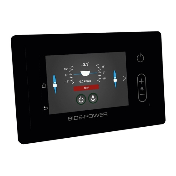
Summary of Contents for Side-Power TP-43A
- Page 1 Operation and User guide Stabilizer Systems US Patent US9527556 AU Patent AU2013335369 Patent pending: PCT/NO2013/050067 Document id: 5288 Revision:...
-
Page 2: Table Of Contents
Contents Information and safety ............................3 Use - Main Menu ..............................5 Alarms and system monitoring ........................... 9 Service and Maintenance ...........................15 Technical Specifications ............................19 Warrany Statement ............................20 Declaration of Conformity ..........................21 Stabilizer Operation and User guide version 5288-2 - 2018... -
Page 3: Information And Safety
Information given or illustrated as IMPORTANT may cause system and property failure if it is disre- garded. NOTE! Information given or illustrated as a NOTE will facilitate correct operation and use of the Side-Power system. Stabilizer Operation and User guide... - Page 4 Safety Before activating the stabilizer system, ensure that: (It is recommended that following notes are included in the boats operator manual) WARNING! • There are no people in the water swimming around the boat • There are no risk of the fins hitting anything, the dock, dock mooring lines or any other submerged objects close to the boat when they start moving.
-
Page 5: Use - Main Menu
BASIC PANEL GUIDE 1. Front screen Fin status, 2 or 4 fins Roll angle Speed Status Panel, ON/OFF Home screen Panel brightness Return Stabilizers ON/OFF At Anchor (Activation) 1.1. Status screen (Touch arrow/triangle on the right) Green light is indicating: GPS available Powerpack VFD enabled Powerpack VFD ready... - Page 6 BASIC PANEL GUIDE 2. ACTIVATE Stabilizers From HOME menu: Touch STABILIZER 2.1. Fins are locked and system in OFF status 2.2. Activate Stabilizers to CRUISING mode: Touch ON/OFF button - system is starting 2.3. Stabilizers are active in CRUISING mode Usually in use from 3/4 knots and up.
- Page 7 Alarm codes and troubleshooting actions are shown in user man- ual. Alarm actions will also be presented in this screen. Contact Side-Power representative. Touch close to finish alarm acknowledgement 4.4. All alarms are acknowledged For fault codes, troubleshooting and advanced panel information please contact your Side-Power representative.
- Page 8 5. VIEW HISTORICAL ALARMS 5.1 Go to home page - Scroll to System devices - Touch System devices 5.2 Touch desired device(s) 5.3 Historical Alarms pop(s) up - Touch Historical alarms 5.4 Historical Alarms is shown - Touch Alarm(s) to view more information 5.5 Alarm details are shown - Touch close to return to list.
-
Page 9: Alarms And System Monitoring
Alarms and System monitoring If an alarm occurs so the stabilizer system is not running, but the fins are centred and locked, you can operate the boat normally, remembering the general warning about high speeds and inactive stabiliz- ers. See Alarm list and boat handling restrictions in table below for more details. WARNING! If the fins are NOT centred and locked, do NOT run forward in more than the minimum necessary steering speed... - Page 10 Cause Action Fault Code Boat handling 100.0.0 System Error - - Internal Error -Consult Side-Power dealer -Check if GW-1 status is ok by checking the GW-1 status No NMEA2000 (pgn127493) LED (See GW-1 user NMEA2000 Transmission transmission message received for manual).
- Page 11 FCU Encoder Fin bow port Encoder position is outside the end stop pulleys. 45001.100.22 Out off position position. -Consult Side-Power dealer -Run bleeding to get rid of air in the hydraulic system -Check encoder belt and pulleys. -Check if something is...
- Page 12 Encoder position is outside the end stop pulleys. 45001.103.22 starboard Out off position position. -Consult Side-Power dealer FCU communication lost. Trigger if no FCU is detected for 25 seconds at startup or after 1.5 seconds with no FCU Communication Fin bow communication during normal operation.
- Page 13 -Check cabling between SCU FCU FW upgrade Fin bow and FCU 45012.100.200 port Timeout SCU failed to upgrade the FCU FW. -Consult Side-Power dealer -Check cabling between SCU FCU FW upgrade Fin bow and FCU 45012.101.200 starboard Timeout SCU failed to upgrade the FCU FW.
- Page 14 Alarms and System monitoring - PHC-3 PHC-3 Fault Code Description Cause Action -Limit use of thruster -Inspect hydraulic oil level 10500.0.10 PHC Oil Level - Level Low Hydraulic oil level is low -Check system for leaks and refill hydraulic oil -Sensor not connected or wire break.
-
Page 15: Service And Maintenance
Service and Maintenance STABILIZER SYSTEM MAINTENANCE FIN ACTUATOR UNITS The stabilizer system is in general a low maintenance product, but as all moving parts some degree of preventive maintenance will increase the lifetime and reliability of the system. A chart for recommended check and service points is thereby offered at the end of this section. For all new installations, or after a major parts change, a basic check should be done after the first 100 hours of operation or after the first week of proper use: • Check that all hydraulic fittings are tight. - Page 16 The maintenance schedules in this section indicate the recommended preventative maintenance intervals for equipment supplied by Side-Power. Components utilized in Side-Power Stabilizer Systems but not supplied by Side-Power are not included in the maintenance schedule or under any Side-Power warranty.
- Page 17 Onboard maintenance possible at sea No shore support required Shore supported maintenance and corrective measures Trained personnel required - Side-Power personnel or equivalent Dry - Vessel must be out of water to perform task Wet - Vessel can be in water to perform task A.
- Page 18 Service and Maintenance STABILIZER SYSTEM MAINTENANCE C. HYDRAULIC POWER UNIT Ser- When When Months/ Maintenance schedule vice out of 250h 500h 2000h 4000h 8000h 12000h required Year level water 1. Inspect the Dirt Indicator of the return 6/0.5 fi lter, replace when required 2.
-
Page 19: Technical Specifications
Technical Specifications Stabilizer Panel: TP-43A Input voltage 8-31VDC Power consumption <3.5W Operating temperature -10 to 70 degrees C Storage temperature -30 to 80 degrees C IP rating front IP67 IP rating rear IP66 Humidity max 95% RH Weight 310g Measurements... -
Page 20: Warrany Statement
Warranty Statement 1. The equipment manufactured by Sleipner Motor AS (The “Warrantor”) is warranted to be free from defects in workmanship and materials under normal use and service. 2. This Warranty is in effect for of two years (Leisure Use) or one year (Commercial use) from the date of purchase by the user. Proof of purchase must be included, to establish that it is inside the warranty period. -
Page 21: Declaration Of Conformity
Side-Power Stabilizer System Vector Fin kit VF1950 Side-Power Stabilizer System Vector Fin kit with the following control systems and optional installation accessories: Side-Power Stabilizer Control System Stabilizer Control Unit Side-Power Stabilizer Control System Fin Control Unit TP-43 Panel Side-Power Stabilizer Control System... - Page 22 Stabilizer Operation and User guide version 5288-2 - 2018...
- Page 23 Stabilizer Operation and User guide version 5288-2 - 2018...
- Page 24 Worldwide sales and service www.side-power.com SLEIPNER MOTOR AS P.O. Box 519 N-1612 Fredrikstad Norway The information given in the document was correct at the time it was published. However, Sleipner Motor AS can not accept liability for any inaccuracies or omissions it may contain.
Need help?
Do you have a question about the TP-43A and is the answer not in the manual?
Questions and answers