Side-Power S-link PJC-212 Installation And User Manual
Hide thumbs
Also See for S-link PJC-212:
- Installation and user manual (24 pages) ,
- Installation and user manual (13 pages) ,
- User info (4 pages)
Advertisement
Advertisement
Table of Contents

Subscribe to Our Youtube Channel
Related Manuals for Side-Power S-link PJC-212


Summary of Contents for Side-Power S-link PJC-212
-
Page 1: Control Panel
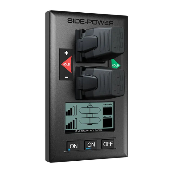
PJC-212 S-link SIDE-POWER Control Panel Thruster Systems Installation and user's manual v 1.1.5 SLEIPNER MOTOR AS P.O. Box 519 N-1612 Fredrikstad Norway Tel: +47 69 30 00 60 w w w . s i d e - p o w e r . c o m... - Page 2 • Hold - function for easy docking, runs thrusters at selected power • Back-lit LCD display with instant feedback System status Amount of thrust & direction of thrust Thruster temperature Battery supply voltage to thrusters - Monitoring of Automatic Mainswitch (informs if the fuse has blown or the manual override is activated) • Interactive multi-language menus • CAN-Bus communication with thrusters and accessories • Plug & play cables, waterproof and compact connectors • Diagnostics via panel • Built-in audible alarm “buzzer” • Connector for external “buzzer”/loud audible alarms • Supports Side-Power retractable thrusters with or without Speed Control DO NOT connect any other control equipment to the S-link controlled products except Side-Power original S-link products or via a Side-Power supplied interface product made for interfacing with other controls. Any attempt to directly control or at all connect into the S-link control system without the designated and approved interface, will render all warranties and responsibilities for the complete line of Side-Power products connected void and null. If you are interfacing by agreement with Sleipner and through a designated and approved interface, you are still required to also install an original Sidepower control panel to enable efficient troubleshooting if necessary Speed control joystick for Holding function for auto- bow thruster running of bow and stern thrusters together in the Speed control joystick for...
-
Page 3: Display In Normal Use
DISPLAY IN NORMAL USE: Bow thruster information Stern thruster information Battery sup- Remaining run Thrust power Battery sup- Remaining run Thrust power ply performance time of thruster and direction ply performance time of thruster and direction based on deliv- based on the based on deliv- based on the ered voltage to electric motors ered voltage to electric motors thruster. As the heat at present. thruster. As the heat at present. battery empties, As bars empties battery empties, As bars empties you have less you have less run you have less you have less run power and less... -
Page 4: Display When Alarms
DISPLAY WHEN ALARMS: When there is a problem or a fault, the panel will show this alarm situation by changing LCD display backlight to red color. The panel will also change to show “Alarm Info” beneath the “boat”, indicating that by pressing the corresponding button (centre ON) you will get information about what the problem is (example below). MENU MENU If the problem is that the voltage delivered from the batteries are too low for the thruster to be allowed to run, this is shown directly on the display by the battery that is not delivering being replaced by the alarm sign (see example). If the issue is something else, the alarm signal will replace the remaining run time indicator for the thruster / system that is causing the alarm. When using the “HOLD” function, the internal and external (if fitted) buzzer will give the following warning signals: Voltage below 9.3V/17.5V or temperature above 90 C (80 C for PPC800 FW V1.013 or older/ (12V/24V system) SR150000 FW V1.006 or older): Single beep every 2.4 seconds Voltage below 8.9V/16.3V or temperature above 100 C (90 C for PPC800 FW V1.013 or older/... -
Page 5: Menu System
MENU SYSTEM: Access menu system by pressing Menu button (middle ‘ON’ button) for 3 seconds Move around in menus by using joysticks Follow instructions on the screen and press buttons as indicated on LCD screen MENU LANGUAGE Choose language by moving bow joystick: English, Norwegian, German, French, Spanish and Italian. LANGUAGE SETUP Pin code is required to enter SETUP. - Page 6 SRH: On/Off Hydraulic retract with crossover and no need for PHC024 controller. SRHP: Proportional Hydraulic retact. This needs the SETUP PHC024 controller. (cont.) SRVP 80/100: Retract SR150000 with PPC800, both de- vices needs to be set to SRVP 80/100. WHEN INSTALLING A RETRACT THRUSTER WITH SPEED CONTROL (PPC800), DO NOT TRY TO RUN THE THRUSTER UNTIL YOU HAVE COMPLETED THE ENTIRE SETUP PROCEDURE CORRECTLY! This is to prevent damage to the thruster caused by run- ning the thruster while the retract mechanism is not fully opened. Save: Saves changes and quit editing. Select: Switch between Location, Retract and Retract set- tings.
- Page 7 RADIO REMOTE SETUP Adjusts the amount of thrust which the ON/OFF remote control will run at. Use joysticks to adjust applied thrust SETUP OK: Saves changes and returns to “SETUP”-menu (cont.) Cancel: Returns to “SETUP”-menu without saving changes Any changes made will be relayed to 8730 INTERFACE units with Firmware 1.203 or newer INFO The info selection is a service screen. Choose the Info screen if you wish to check your system. When in this screen you will be able to run the thrusters individually with the joysticks or simul- INFO taneously with the “Hold” function. You will be able to see three screens by pressing the “more” but- ton 1st. screen : Control panel info: - Firmware and Hardware version - Serial number - S-link voltage 2nd & 3rd screens: Bow and stern thruster information - Motor temperature - Controller temperature - Actual voltage - Thrust percentage it is running at - Current consumption & watt at present. More: Changes to next information page Cancel: Returns to main menu DEFAULT SETTINGS Reset all settings to factory default - follow instructions on screen Start: Resets system to default factory settings DEFAULT Cancel: Returns to main menu without changes PANEL SETUP BACKLIGHT LEVEL PANEL...
- Page 8 Error message overview Errors shown SR80 SR130 Description Action in display 8977 SR100 SR170 SR210 SRV80 SRV100 Motor Motor current over Thruster must be serviced by au- Overcurrent 1400A thorized personel, reset or PPC800 power OFF/ON Motor Motor temperature Motor cool down below 115°C Overtemp have been over 130 (100 C for PPC800 FW 1.013 or (110 C for PPC800 older/SR150000 FW1.006 or older) FW 1.013or older/ SR150000 FW1.006 or older) Controller PPC800 temperature PPC800 cool down below 45°C Overtemp have been over 80 Controller...
- Page 9 Sample S-link system PJC-212 1.1.5 - 2012...
- Page 10 Connections for optional external buzzer/audible alarm External alarm/buzzer connection (S-link) Supply +12V / 24V DC Internal fuse/relay External alarm buzzer 12V / 24V DC - max 0,5A PJC-212 1.1.5 - 2012...
- Page 11 Measurements PJC-212 1.1.5 - 2012...
- Page 12 SIDE-POWER SERVICE CENTRES Argentina Estonia/Latvia/Lithuania Japan Spain Trimer SA Miltec Systems OÜ Turtle Marine Inc. Imnasa Marine Products Buenos Aires Tallin Nagasaki Girona Tel:+54 11 4580 0444 Tel: +372 5013997 Tel:+81 95 840 7977 Tel:+34 902 300 214 Fax:+54 11 4580 0440...
Need help?
Do you have a question about the S-link PJC-212 and is the answer not in the manual?
Questions and answers