Table of Contents
Advertisement
Quick Links
Advertisement
Table of Contents

Subscribe to Our Youtube Channel
Summary of Contents for Side-Power PJC322
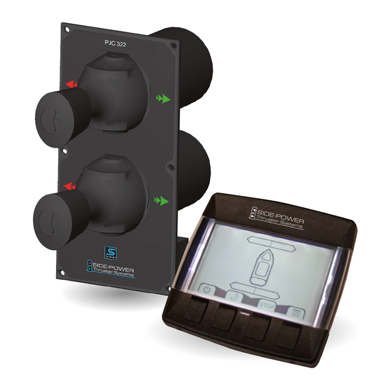
- Page 1 PJC321, PJC322 PJC321-L, PJC322-L PJC321-MCL2, PJC322-MCL2 SIDE-POWER S-link Thruster Systems Control Panel Installation and user’s manual SLEIPNER MOTOR AS P.O. Box 519 N-1612 Fredrikstad Norway www.side-power.com Document id: 2921 Revision: © Sleipner Motor AS 2018...
-
Page 2: Table Of Contents
Panel dimensions PJC321 ................................... 13 Panel dimensions PJC321-L/PJC322-L ..............................14 Panel dimensions PJC321-MCL2/PJC322-MCL2 ............................. 15 S-Link overview ......................................16 Internal wiring diagram PJC321, PJC322 ..............................17 Internal wiring diagram PJC321-L, PJC322-L............................18 Internal wiring diagram PJC321-MCL2, PJC322-MCL2 ........................... 19 DECLARATION OF CONFORMITY SAMSVARSERKLÆRING... -
Page 3: Product Features
Side-Power products connected void and null. If you are interfacing by agreement with Sleipner and through a designated and approved interface, you are still required to also install an original Side-Power control panel to enable efficient troubleshooting if necessary... -
Page 4: Technical Specifications
Technical specifications Description Value Supply Voltage 9-63 Vdc/6.5 Watts Operating temperature –40°C to +70°C [–40°F to +158°F] Storage temperature –40°C to +85°C [–40°F to +176°F] IP Rating IP67 above panel EMC tested Acc. to EN 13309, ISO 14982, ISO 13766 ESD tested Acc. -
Page 5: Display Warnings And Alarms
Display Warnings & Alarms FILTER MONITORING WARNINGS (IF SENSORS ARE INSTALLED) PRESSURE FILTER: Pressure filter symbol (upper right) will blink when filter change is due. In ad- dition red LEDs on both sides of the panel will blink and the external buzzer is activated. -
Page 6: Menu System
Display Warnings & Alarms AC MOTOR ALARMS HYDRAULIC AC MOTOR POWER PACK OVERTEMP: The overtemp symbol will show in the upper right corner of the dis- PANEL play when the AC motor temperature is above 120°C and automati- cally reset when temperature goes below 110°C. HYDRAULIC AC MOTOR POWER PACK TEMP SENSOR: The AC motor temp sensor fail symbol will show in the upper right corner if the system is set up with an hydraulic AC motor power... -
Page 7: Display Settings
Menu System 1/5 Language Choose between English or Norwegian. The setting will not affect other panels in the system. PANEL 2/5 Display settings Set contrast and backlight level for Daytime/Night modes Settings will not affect other panels in the system. Press to start adjustment - Press + or - to adjust contrast or backlight. - Page 8 Menu System 1.2 Pump Control (PTO Mounted Pump) Values: Power Save(default)/Always ON When «Pump Control» is set to « Power Save», the system will automati- PANEL cally control load sharing between two PTO pumps by deactivating the secondPTO pump when not needed (two PTO pumps/control valves required) to reduce heat generation in the system and save fuel/en- ergy.
- Page 9 Menu System 1.8 Thruster Stern (only available for PHC024 with FW V1.105 or higher) Values: WO/Bypass Valve (default)/ W/Bypass Valve PANEL All 513mm (20inch) tunnel and 610mm (24inch) tunnel thrusters, are supplied with hydraulic bypass/crossover valve and must be set to “W/Bypass Valve”.
-
Page 10: Service Menu
Menu System SERVICE MENU (Systems with one oil tank) Access SERVICE MENU by pressing MENU button Shows oil pressure and temperature in the hydraulic tank as PANEL well as the serial number of the panel. Thrusters can be operated while this display is shown. Exit Service Menu by pressing SERVICE MENU (Systems with two oil tanks) Shows oil pressure and temperature in both hydraulic tanks as... -
Page 11: Panel Dimensions
Panel Dimensions PJC321/322 2921-5 - 2018... -
Page 12: Panel Dimensions Pjc322
Panel Dimensions, PJC322 IMPORTANT! In case of mounting in This template is for meas- rough and humid weather conditions, urements use only! apply sealant under the panel mating Use external template surface to avoid water ingress. when mounting ... -
Page 13: Panel Dimensions Pjc321
Panel Dimensions, PJC321 IMPORTANT! In case of mounting in This template is for meas- urements use only! rough and humid weather conditions, Use external template apply sealant under the panel mating when mounting surface to avoid water ingress. ... -
Page 14: Panel Dimensions Pjc321-L/Pjc322-L
Panel Dimensions, PJC321-L, PJC322-L LF90 Control lever LF90 Control lever This template is for meas- IMPORTANT! In case of mounting in urements use only! rough and humid weather conditions, Use external template apply sealant under the panel mating when mounting surface to avoid water ingress. -
Page 15: Panel Dimensions Pjc321-Mcl2/Pjc322-Mcl2
Examples of standard versions of the MCL2 control lever. The picture differences. Specifications for the non-visual properties (d-e-f) are fou Examples of standard versions of the MCL2 control lever. The picture Panel Dimensions PJC321-MCL2, PJC322-MCL2 differences. Specifications for the non-visual properties (d-e-f) are fou Longitudinal motion... -
Page 16: S-Link Overview
S-Link overview PJC321/322 2921-5 - 2018... -
Page 17: Internal Wiring Diagram Pjc321, Pjc322
Internal Wiring Diagram PJC321, PJC322 PJC321/322 2921-5 - 2018... -
Page 18: Internal Wiring Diagram Pjc321-L, Pjc322-L
Internal Wiring Diagram PJC321-L, PJC322-L PJC321/322 2921-5 - 2018... -
Page 19: Internal Wiring Diagram Pjc321-Mcl2, Pjc322-Mcl2
Internal Wiring Diagram PJC321-MCL2, PJC322-MCL2 PJC321/322 2921-5 - 2018... -
Page 20: Sleipner Motor As
Worldwide sales and service www.side-power.com SLEIPNER MOTOR AS P.O. Box 519 N-1612 Fredrikstad Norway The information given in the document was correct at the time it was published. However, Sleipner Motor AS can not accept liability for any inaccuracies or omissions it may contain.


Need help?
Do you have a question about the PJC322 and is the answer not in the manual?
Questions and answers