
Related Manuals for Boser HS-2613


Summary of Contents for Boser HS-2613
- Page 1 HS-2613 VIA V4 Eden processor Embedded Engine Board •CompactFlash•8-bit I/O•DVI-D/CRT/LVDS•TV-Out• •Dual LAN•Audio•SATA•ATA/33/66/100• •RS-232/422/485•4 COM•5 USB2.0• •PCI-104•WDT•H/W Monitor•...
- Page 2 Unauthorized reproduction, transmission, translation, and storage of any form and means (i.e., electronic, mechanical, photocopying, recording) of this document, in whole or partly, is prohibited, unless granted permission by BOSER Technology Co., Ltd. reserves the right to change or improve the contents of BOSER Technology Co., Ltd.
-
Page 3: Table Of Contents
Table of Contents Chapter 1 General Description ........1 1.1 Major Features ............... 2 1.2 Specifications ................ 3 1.3 Board Dimensions..............4 Chapter 2 Unpacking ..........5 2.1 Opening the Delivery Package..........5 2.2 Inspection................5 Chapter 3 Hardware Installation ......7 3.1 Before Installation ..............7 3.2 Board Layout ................. - Page 4 Chapter 4 AMI BIOS Setup ........29 4.1 Starting Setup..............29 4.2 Using Setup ................. 30 4.3 Main Menu................31 4.4 Advanced Settings .............. 32 4.5 Advanced PCI/PnP Settings..........37 4.6 Boot Settings ............... 38 4.7 Security Settings ..............39 4.8 Advanced Chipset Settings..........
- Page 5 Declaration of Conformity -- CE Mark BOSER Technology hereby acknowledges that compliance testing in accordance with applicable standards of the EU’s EMC Directive, 89/336/EEC, was successfully completed on a sample of the equipment identified below: Equipment Class: Information Technology Equipment...
- Page 6 Fasten the ALLIGATOR clip of the strap to the end of the shielded wire lead from a grounded object. Please wear and connect the strap before handle the HS-2613 to ensure harmlessly discharge any static electricity through the strap.
-
Page 7: Chapter 1 General Description
LAN, audio, SATA, 4 COM, USB2.0, and PCI-104 interfaces. Its onboard ATA/33/66/100 to IDE drive interface architecture allows the HS-2613 to support data transfers of 33 or 66MB/sec. to one IDE drive connection. Designed with the VIA CX700(M), the board supports VIA V4 Eden 1GHz CPU. -
Page 8: Major Features
Major Features The HS-2613 comes with the following features: VIA V4 Eden processor 1GHz, supports 400MHz FSB 1 x SO-DIMM up to 1GB DDR2 SDRAM VIA CX700(M) system chipset VIA CX700(M) integrated VGA for CRT & LVDS 2 x 10/100 Mbps ethernet AC’97 audio codec... -
Page 9: Specifications
Specifications System VIA V4 Eden processor 1GHz Front Side Bus 400MHz FSB BIOS Award PnP Flash BIOS System Chipset: VIA CX700(M) I/O Chipset Winbond W83697UG System Memory 1 x 200-pin SO-DIMM socket DDR2 533MHz up to 1GB Storage 1 x Type II CF socket Watchdog Timer Software programmable time-out intervals from 1~255 sec. -
Page 10: Board Dimensions
Display Chipset VIA CX700(M) Display Memory 32/64/128MB video memory LVDS 24-bit single/dual-channel TV-Out Provides PAL or NTSC TV systems DVI Chipset VIA CX700(M) (option) Resolution CRT Mode: 1920 x 1440 LVDS Mode: 1600 x 1200 Audio Chipset VIA VT1708A Audio Interface (w/pin header) MIC In, Line Out Ethernet Chipset... -
Page 11: Chapter 2 Unpacking
Chapter 2 Unpacking Opening the Delivery Package The HS-2613 is packed in an anti-static bag. The board has components that are easily damaged by static electricity. Do not remove the anti-static wrapping until proper precautions have been taken. Safety Instructions in front of this manual describe anti-static precautions and procedures. - Page 12 Cables Package Description QTY. SATA cable 50cm (w/Lock) COM DB9-10P(2.0-pitch) 15cm SPK 8P(2.0) phone jack x 2 30cm 1-to-2 Mini DIN cable 19cm 4-pin to 4-pin terminal block power cable It is recommended that you keep all the parts of the delivery package intact and store them in a safe/dry place for any unforeseen event requiring the return shipment of the product.
-
Page 13: Chapter 3 Hardware Installation
Chapter 3 Hardware Installation This chapter provides the information on how to install the hardware using the HS-2613. This chapter also contains information related to jumper settings of switch, and watchdog timer selection etc. Before Installation After confirming your package contents, you are now ready to install your hardware. -
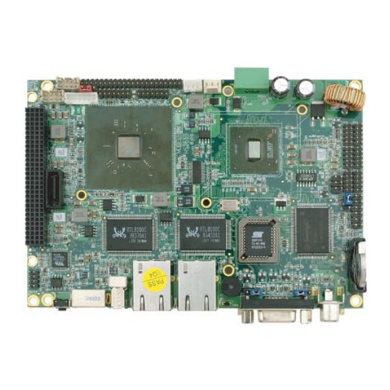
Page 14: Board Layout
Board Layout... -
Page 15: Jumper List
Jumper List Jumper Default Setting Setting Page Panel Voltage Select: +3.3V Short 1-2 CF Use Master/Slave Select: Slave Short 2-3 Display Out Function Select: CRT Short 1-2 Clear CMOS: Normal Operation Short 1-2 COM2 Use RS-232 or RS-422/485 Select: CN25 Open RS-232 Connector List... -
Page 16: Configuring The Cpu
CN25 offers an internal 10-pin CRT connector and CN6/CN9 are the LVDS interface connectors onboard reserved for flat panel installation. HS-2613 also provides DVI-D function (PCB v1.2 or above). There is an option cable (291-13010040G for this function use (CN10+CN30). - Page 17 If you want to use 48-bit dual channel LVDS panel, please use CN10 and CN12 combined. The HS-2613 has an onboard jumper that selects the working voltage of the flat panel connected to the system. Jumper JP1 offers two voltage settings for the user.
-
Page 18: Ide Drive Connector
IDE Drive Connector CN11 is a 2.0-pitch 44-pin connector which support up to 2 ATA/33/66/100 IDE drives can be connected to the HS-2613 via CN11. CN11: IDE Connector Description Description Reset PDD7 PDD8 PDD6 PDD9 PDD5 PDD10 PDD4 PDD11 PDD3... -
Page 19: Serial Port Connectors
SATATXP SATATXN SATARXN SATARXP 3.10 Serial Port Connectors The HS-2613 offers NS16C550 compatible UARTs with Read/ Receive 16-byte FIFO serial ports and four internal 10-pin headers and one RS-422/485 connector. CN24/CN20/CN21/CN26: COM 1 ~ COM 4 Connector (5x2 Header) PIN Description PIN Description... -
Page 20: Ethernet Connector
4-wires point-to-point full duplex RS-422/485 Typical RS-485 2-wires Mutildrop Network 3.11 Ethernet Connector The HS-2613 provides two RJ-45 connectors for 10/100 Based LAN. Please refer to the following for its pin information. When installs OS, this driver namely can automatically install. User does not need to renewal. -
Page 21: Usb Port
Before turn on the power of system, please set JP5 to Short 1-2 for normal operation. 3.14 Power and Fan Connectors HS-2613 provides one 4-pin power in at CN15, one 3-pin power in at CN29. Connector FN2 onboard HS-2613 is a 3-pin fan power output connector. -
Page 22: Keyboard/Mouse Connectors
Fan In CN15: 4pin Power Connector PIN Description DC In DC In 3.15 Keyboard/Mouse Connectors The CN8 is a PS/2 6-pin Mini DIN connector for HS-2613. CN8: PS/2 6-pin Mini DIN Keyboard/Mouse Connector Description Keyboard Data Mouse Data Keyboard Clock... -
Page 23: System Front Panel Control
3.16 System Front Panel Control The HS-2613 has front panel control at location CN23 that indicates the power-on status. CN5: External Reset Button Description Reset Switch CN23: System Front Panel Control Description Description 330Ω pull VCC Speaker HDD LED ATX Power Button 330Ω... -
Page 24: Watchdog Timer
The following sample programs show how to enable, disable and refresh the watchdog timer: .286 .MODEL SMALL .DATA ;this is data area db '------------------------------------------------------',0ah,0dh,'$' copyright db '|Copyright by Boser technology write by Richard |',0ah,0dh,'$' db '------------------------------------------------------',0ah,0dh,'$' port 04Eh ;W83697H Chipset port datao 04Fh ;data port .CODE... -
Page 25: Tv-Out Function
User can also use AL, 00H’s defined time for reset purposes, e.g.00H for Disable, 01H = 1sec, 02H=2sec….FFH=255sec. 3.18 TV-Out Function The HS-2613 can support TV-out function whose input could be up to 800 x 600 graphics resolutions. World Wide Video standards are supported including NTSC-M (North America, Taiwan), NTSC-J (Japan), PAL-b, D, G, H, I (Europe, Asia), PAL-M (Brazil), PAL-N (Uruguay, Paraguay) and PAL-NC (Argentina). -
Page 26: Pci-104 Connector
3.19 PCI-104 Connector The HS-2613 provides one PCI-104 connector, at location CN2. CN2: PCI-104 Connector Description Description CBE0# AD11 AD14 AD13 +3.3V CBE1# SERR# PERR# STOP# +3.3V +3.3V TRDY- FRAME# AD16 AD18 +3.3V AD21 AD20 +3.3V AD23 IDSEL0 AD24 CBE3#... - Page 27 Description Description AD10 PULL VCC AD12 AD15 +3.3V +3.3V PULL VCC PULL VCC DEVSEL# IRDY# +3.3V +3.3V CBE2# AD17 AD19 AD22 +3.3V IDSEL1 IDSEL2 IDSEL3 AD25 AD28 AD27 AD31 REQA GNT0# GNTB PCICLKA PCICLKC PCIRST# INTR_B# INTR_C# INTR_C#...
-
Page 28: Audio Connectors
MIC IN L MIC IN R 3.21 CompactFlash Socket The HS-2613 also offers a Type II CompactFlash socket is IDE interface located at the solder side of the board. The designated CN28, once soldered with an adapter, can hold CompactFlash cards of various sizes. - Page 29 CN28: CompactFlash Socket Description Description DATA3 DATA4 DATA5 DATA6 DATA7 SDCS1# SDA2 SDA1 SDA0 DATA0 DATA1 DATA2 470Ω pull GND DATA11 DATA12 DATA13 DATA14 DATA15 SDCS3# EWE0 RESET IORDY DACK IDE LED PDIAG DATA8 DATA9 DATA10 NOTE: When use CF card, IDE device function will be disabled.
-
Page 30: 8-Bit I/O Function
3.22 8-bit I/O Function The HS-2613 offers one 8-bit input/output port by parallel port. CN19: 8-bit Input/Output PIN Description PIN Description .286 .MODEL SMALL .DATA ;this is data area port 0378h ;print port can be change to 278h .CODE print... - Page 31 al, 1 call delay dx, al loop ;;ROL push cx, 08h al, 1 dx, al call delay loop ;;-------------------- ;;-------------------- ;;ROR cx, 08h al, 1 call delay dx, al loop ;;ROL push cx, 08h al, 1 dx, al call delay loop ;;-------------------- ;;--------------------...
- Page 32 call delay dx, al loop ;;ROL push cx, 08h al, 1 dx, al call delay loop ;;-------------------- ;;-------------------- ;;ROR cx, 08h al, 1 call delay dx, al loop ;;ROL push cx, 08h al, 1 dx, al call delay loop ;;-------------------- ;;-------------------- ;;ROR cx, 08h...
- Page 33 dx, al loop ;;ROL push cx, 08h al, 1 dx, al call delay loop ;;-------------------- ;flash LED 3 time cx, 01h al, 0ffh dx, al call delay al,0h dx, al call delay loop ah, 4ch ;go back to dos .stack begin endp end begin...
- Page 34 This page is the blank page.
-
Page 35: Chapter 4 Ami Bios Setup
Chapter 4 AMI BIOS Setup The HS-2613 uses AMI BIOS for the system configuration. The AMI BIOS setup program is designed to provide the maximum flexibility in configuring the system by offering various options that could be selected for end-user requirements. This chapter is written to assist you in the proper usage of these features. -
Page 36: Using Setup
Using Setup In general, you use the arrow keys to highlight items, press <Enter> to select, use the <PageUp> and <PageDown> keys to change entries, and press <Esc> to quit. The following table provides more detail about how to navigate in the Setup program using the keyboard. Move to previous item ↑... -
Page 37: Main Menu
Main Menu Once you enter the AMI BIOS CMOS Setup Utility, the Main Menu will appear on the screen. The Main Menu allows you to select from several setup functions and two exit choices. Use the arrow keys to select among the items and press <Enter>... -
Page 38: Advanced Settings
Advanced Settings This section allows you to configure your system for the basic operation. You have the opportunity to select the system’s default speed, boot-up sequence, keyboard operation, shadowing and security. BIOS SETUP UTILITY Main Advanced PCIPnP Boot Security Chipset Exit Advanced Settings WARNING: Setting wrong values in below sections... - Page 39 BIOS SETUP UTILITY Main Advanced PCIPnP Boot Security Chipset Exit IDE Configuration Parallel ATA IDE device Primary IDE Master : [Not Detected] Primary IDE Slave : [Not Detected] Secondary IDE Master : [Not Detected] Secondary IDE Slave : [Not Detected] Parallel ATA IDE Controller [Both] Hard Disk Write Protect...
- Page 40 BIOS SETUP UTILITY Main Advanced PCIPnP Boot Security Chipset Exit ACPI Settings ACPI Aware O/S [No] Select Screen Select Item Change Field Select Field General Help Save and Exit Exit v02.59 (C)Copyright 1985-2005, American Megatrends, Inc.
- Page 41 BIOS SETUP UTILITY Main Advanced PCIPnP Boot Security Chipset Exit Power Management/APM [Enabled] Power Button Mode [On/Off] Suspend Power Saving Type [C3] Restore on AC/Power Loss [Power On] Manual Throttle Ratio [50%-56.25%] System Thermal [Disabled] Thermal Active Temperature [65°C/149°F] THRM throttle Ratio [50%-56.25%] Standby Time Out [Disabled]...
- Page 42 BIOS SETUP UTILITY Main Advanced PCIPnP Boot Security Chipset Exit USB Configuration Module Version – 2.24.0-11.4 USB Devices Enabled: None USB 1.1 Ports Configuration [USB 6 Ports] USB 2.0 Ports Enable [Enabled] Legacy USB Support [Enabled] Select Screen USB 2.0 Controller Mode [FullSpeed] Select Item Change Field...
-
Page 43: Advanced Pci/Pnp Settings
Advanced PCI/PnP Settings This section describes configuring the PCI bus system. PCI, or Personal Computer Interconnect, is a system that allows I/O devices to operate at speeds nearing the speed the CPU itself uses when communicating with its own special components. This section covers some very technical items and it is strongly recommended that only experienced users should make any changes to the default settings. -
Page 44: Boot Settings
Boot Settings BIOS SETUP UTILITY Main Advanced PCIPnP Boot Security Chipset Exit Boot Settings Boot Settings Configuration Boot Device Priority Removable Drives Select Screen Select Item Change Field Select Field General Help Save and Exit Exit v02.59 (C)Copyright 1985-2005, American Megatrends, Inc. BIOS SETUP UTILITY Main Advanced... -
Page 45: Security Settings
BIOS SETUP UTILITY Main Advanced PCIPnP Boot Security Chipset Exit Boot Device Priority 1st Boot Device [1st FLOPPY DRIVE] Select Screen Select Item Change Field Select Field General Help Save and Exit Exit v02.59 (C)Copyright 1985-2005, American Megatrends, Inc. BIOS SETUP UTILITY Main Advanced PCIPnP... -
Page 46: Advanced Chipset Settings
Advanced Chipset Settings BIOS SETUP UTILITY Main Advanced PCIPnP Boot Security Chipset Exit Advanced Chipset Settings WARNING: Setting wrong values below sections cause system malfunction. NorthBridge VIA CX700 Configuration SouthBridge VIA CX700 Configuration Select Screen Select Item Change Field Select Field General Help Save and Exit Exit... - Page 47 BIOS SETUP UTILITY Main Advanced PCIPnP Boot Security Chipset Exit DRAM Frequency/Timing Configuration DRAM Frequency [Auto] DRAM Timing [Auto] DRAM Command Rate [2T Command] RDSAIT/RDSBIT mode [Auto] Memory Chip Driving [Normal] DDR2 Memory Chip ODT [Auto] DDR DQSBAR [Disabled] BA0 SEL [A13] BA1 SEL [A14]...
- Page 48 BIOS SETUP UTILITY Main Advanced PCIPnP Boot Security Chipset Exit V-Link & PCI Bus Configuration PCI Master 0 WS Write [Enabled] V-Link mode selection [Auto] V-Link 8X Supported [Enabled] V-Link Data 2X Support [Disabled] DRDY Timing [Default] RCONV [Enabled] Select Screen Dynamic CKE select [Auto] Select Item...
-
Page 49: Exit Options
Exit Options BIOS SETUP UTILITY Main Advanced PCIPnP Boot Security Chipset Exit Exit Options Save Changes and Exit Discard Changes and Exit Discard Changes Load Optimal Defaults Load Failsafe Defaults Select Screen Select Item - Change Field Select Field General Help Save and Exit Exit v02.59 (C)Copyright 1985-2005, American Megatrends, Inc. - Page 50 This page is the blank page.
-
Page 51: Chapter 5 Award Bios Setup
Chapter 5 AWARD BIOS Setup The HS-2613 uses AWARD BIOS for the system configuration. The AWARD BIOS setup program is designed to provide the maximum flexibility in configuring the system by offering various options that could be selected for end-user requirements. This chapter is written to assist you in the proper usage of these features. -
Page 52: Using Setup
Using Setup In general, you use the arrow keys to highlight items, press <Enter> to select, use the <PageUp> and <PageDown> keys to change entries, and press <Esc> to quit. The following table provides more detail about how to navigate in the Setup program using the keyboard. Move to previous item ↑... -
Page 53: Main Menu
Main Menu Once you enter the Award BIOS CMOS Setup Utility, the Main Menu will appear on the screen. The Main Menu allows you to select from several setup functions and two exit choices. Use the arrow keys to select among the items and press <Enter> to enter the sub-menu. Phoenix - AwardBIOS CMOS Setup Utility Standard CMOS Features Frequency/Voltage Control... -
Page 54: Standard Cmos Features
Standard CMOS Features The standard CMOS is used for the basic hardware system configuration. The main function is for Data/Time and Floppy/Hard Disk Drive settings. Please refer to the following screen for the setup. When the IDE hard disk drive you are using is larger than 528MB, you must set the HDD mode to LBA mode. -
Page 55: Advanced Bios Features
Advanced BIOS Features This section allows you to configure your system for the basic operation. You have the opportunity to select the system’s default speed, boot-up sequence, keyboard operation, shadowing and security. Phoenix - AwardBIOS CMOS Setup Utility Advanced CMOS Features CPU Feature [Press Enter] Item Help... -
Page 56: Advanced Chipset Features
Advanced Chipset Features This section allows you to configure the system based on the specific features of the installed chipset. This chipset manages bus speeds and the access to the system memory resources, such as DRAM and the external cache. It also coordinates the communications between the conventional ISA and PCI buses. - Page 57 Phoenix - AwardBIOS CMOS Setup Utility AGP & P2P Bridge Control AGP Aperture Size [128M] Item Help AGP3.0 Mode [8X] AGP Driving Control [Auto] AGP Driving Value AGP Fast Write [Disabled] AGP Master 1 WS Write [Enabled] AGP Master 1 WS Read [Enabled] AGP 3.0 Calibration cycle [Enabled]...
-
Page 58: Integrated Peripherals
Integrated Peripherals The IDE hard drive controllers can support up to two separate hard drives. These drives have a master/slave relationship that is determined by the cabling configuration used to attach them to the controller. Your system supports two IDE controllers – a primary and a secondary –... - Page 59 Phoenix - AwardBIOS CMOS Setup Utility VIA OnChip PCI Device Azaliz HDA Controller [Auto] Item Help ↑↓← →: Select Item +/-/PU/PD: Value F10: Save Esc: Quit F1: General Help F5: Previous Values F6: Fail-Safe Defaults F7: Optimized Defaults Phoenix - AwardBIOS CMOS Setup Utility SuperIO Device Onboard Serial Port 1 [3F8/IRQ4]...
-
Page 60: Power Management Setup
Power Management Setup Phoenix - AwardBIOS CMOS Setup Utility Power Management Setup Power Management Option [User Define] Item Help HDD Power Down [Disable] Suspend Mode [Disable] Video Off Option [[Suspend => Off] Video Off Method [V/H SYNC+Blank] MODEM Use IRQ Soft-Off by PWRBTN [[Instant-Off] Run VGABIOS if S3 Resume... -
Page 61: Pnp/Pci Configurations
PnP/PCI Configurations This section describes the configuration of the PCI bus system. Peripheral Components Interconnect (PCI), is a system that allows I/O devices to operate at speeds nearing the speed the CPU itself uses when communicating with its own special components. This section covers some very technical items and it is strongly recommended that only experienced users should make any changes to the default settings. -
Page 62: Pc Health Status
5.10 PC Health Status Phoenix - AwardBIOS CMOS Setup Utility PC Health Status CPU Warning Temperature [Disabled] Item Help Current System Temp. Current CPU1 Temperature Current CPUFAN1 Speed Vcore +3.3V VBAT(V) Shutdown Temperature [Disabled] ↑↓← →: Select Item +/-/PU/PD: Value F10: Save Esc: Quit F1: General Help... -
Page 63: Chapter 6 Software Utilities
Chapter 6 Software Utilities This chapter contains the detailed information about installation procedures of chipset, VGA, LAN, audio and other drivers. The utility CD disk that comes with the package contains an auto-run program that invokes the installation programs for the chipset, VGA, LAN and audio drivers. -
Page 64: Vga Driver Installation
VGA Driver Installation Insert the CD that comes with the board into the CD-ROM drive. Click VGA to install VIA VGA driver. When the display below appears on your screen, setup is ready to install and copy the related files onto your hard drive. -
Page 65: Audio Driver Installation
After the installation finishes, you will be prompted to restart your system. We recommend you to reboot your computer to allow the new settings to take effect. Click on the Finish button to reboot. Audio Driver Installation Insert the CD that comes with the board into the CD-ROM drive. Click Audio to install VIA audio driver. - Page 66 Once the Setup Wizard appears on the screen, make sure to close applications that are running, and then tick Install/Update, and click on the Next> button. Setup Wizard will display the install list. Select on VIA HD…… V1.80a, and then click on Next> to continue.
- Page 67 Make sure the Current Setting is ok, and then click on Next> button. After the audio driver installation finishes, select the Finish button to complete the installation process.
- Page 68 When the display below appears on your screen, tick on Yes, this time only, and then click on Next> to continue. After all installation finish, you will be prompted to start your system, click on the Finish button to reboot.
-
Page 69: Lan Driver Installation
LAN Driver Installation Insert the CD that comes with the board into the CD-ROM drive. Click LAN to install RTL8100C LAN driver. When the dialog box below appears, make sure you close all other Windows applications and click “Next>” to proceed. - Page 70 The Setup Status dialog box then appears on the screen. When setup is finished, please reboot your computer to take the effect.
-
Page 71: Usb2.0 Driver Installation
USB2.0 Driver Installation Insert the CD that comes with the board into the CD-ROM drive. Click USB to install usb driver. Once the Welcome screen appears on the screen, make sure to close applications that are running and then click on Next> button. - Page 72 The Select Components dialog box is now displayed. Select on Install and then click on Next>. After all installation finish, you will be prompted to start your system, click on the Yes button to reboot.
Need help?
Do you have a question about the HS-2613 and is the answer not in the manual?
Questions and answers