
Subscribe to Our Youtube Channel
Related Manuals for Boser HS-2622


Summary of Contents for Boser HS-2622
- Page 1 HS-2622 VIA V4 Eden processor Embedded Engine Board •CompactFlash•CRT/LVDS/DVI• •Dual LAN•Audio•SATA• •RS-232/422/485•6 USB2.0• •WDT•H/W Monitor•...
- Page 2 Unauthorized reproduction, transmission, translation, and storage of any form and means (i.e., electronic, mechanical, photocopying, recording) of this document, in whole or partly, is prohibited, unless granted permission by BOSER Technology Co., Ltd. reserves the right to change or modify the contents of BOSER Technology Co., Ltd.
-
Page 3: Table Of Contents
Table of Contents Chapter 1 General Description ........1 1.1 Specifications ................ 2 1.2 Board Dimensions..............3 Chapter 2 Unpacking ..........5 2.1 Opening the Delivery Package..........5 2.2 Inspection................5 Chapter 3 Hardware Installation ......7 3.1 Before Installation ..............7 3.2 Board Layout ................. 8 3.3 Jumper List ................ - Page 4 Chapter 4 Award BIOS Setup ......... 17 4.1 Starting Setup..............17 4.2 Using Setup ................. 18 4.3 Main Menu................19 4.4 Standard CMOS Features........... 20 4.5 Advanced BIOS Features ........... 21 4.6 Advanced Chipset Features..........22 4.7 Integrated Peripherals ............25 4.8 Power Management Setup ..........
- Page 5 Declaration of Conformity -- CE Mark BOSER Technology hereby acknowledges that compliance testing in accordance with applicable standards of the EU’s EMC Directive, 89/336/EEC, was successfully completed on a sample of the equipment identified below: Equipment Class: Information Technology Equipment...
- Page 6 Fasten the ALLIGATOR clip of the strap to the end of the shielded wire lead from a grounded object. Please wear and connect the strap before handle the HS-2622 to ensure harmlessly discharge any static electricity through the strap.
-
Page 7: Chapter 1 General Description
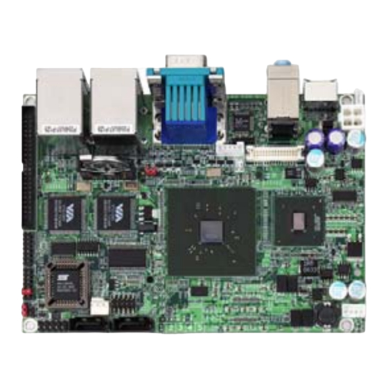
Chapter 1 General Description The HS-2622 is designed in a 3.5” embedded form factor to fit the low power VIA V4 bus Eden processor onboard, to meet today’s demanding pace, and to keep complete compatibility with hardware and software function supported. The onboard devices support VIA Eden 1GHz processor, integrated graphics and dual Ethernet controllers. -
Page 8: Specifications
Specifications CPU: VIA V4 Eden 1.0GHz processor Front Side Bus: 400MHz FSB Memory: 1 x 200-pin SO-DIMM socket support DDR2 400/533 SDRAM, max. up to 1GB memory Chipset: VIA CX700M I/O Chipset: Winbond W83697HG SSD: 1 x CompactFlash socket with ejector at I/O side (shared Master IDE) VGA: VIA CX700M with 128MB shared main memory supports CRT display up to 2048 x 1536... -
Page 9: Board Dimensions
Board Dimensions... - Page 10 This page is the blank page.
-
Page 11: Chapter 2 Unpacking
Chapter 2 Unpacking Opening the Delivery Package The HS-2622 is packed in an anti-static bag. The board has components that are easily damaged by static electricity. Do not remove the anti-static wrapping until proper precautions have been taken. Safety Instructions in front of this manual describe anti-static precautions and procedures. - Page 12 It is recommended that you keep all the parts of the delivery package intact and store them in a safe/dry place for any unforeseen event requiring the return shipment of the product. In case you discover any missing and/or damaged items from the list of items, please contact your dealer immediately.
-
Page 13: Chapter 3 Hardware Installation
Chapter 3 Hardware Installation This chapter provides the information on how to install the hardware using the HS-2622. This chapter also contains information related to jumper settings of switch, and watchdog timer selection etc. Before Installation After confirming your package contents, you are now ready to install your hardware. -
Page 14: Board Layout
Board Layout... -
Page 15: Jumper List
Serial ATA Port CompactFlash Connector ---- Configuring the CPU The HS-2622 embedded with VIA V4 Eden 1.0GHz processor. User don’t need to adjust the frequently and check speed of CPU. System Memory The HS-2622 provides one SO-DDRII socket at locations DIMM1. The... -
Page 16: Vga Controller
VGA Controller The HS-2622 provides two connection methods of a VGA device. CN4(VGA) offers an internal 15-pin CRT connector and CN10 is the LVDS interface connectors onboard reserved for flat panel installation. CN9: Inverter Power Connector Description +3.3V BL On/Off Control... - Page 17 CN10: LVDS Connector Description Description A_DATA0-/DVI_TLC- B_DATA0- A_DATA0+/DVI_TLC+ B_DATA0+ A_DATA1-/DVI_TDC0- B_DATA1- A_DATA1+/DVI_TDC0+ B_DATA1+ A_DATA2-/DVI_TDC1- B_DATA2- A_DATA2+/DVI_TDC1+ B_DATA2+ A_DATA3- B_DATA3- A_DATA3+ B_DATA3+ A_CLK-/DVI_TDC2- B_CLK- A_CLK+/DVI_TDC2+ B_CLK+ LVDS_VCC LVDS_VCC +5V(DVI) +5V(DVI) DVI_CLK LDDC_CLKL DVI_DATA LDDC_DATA_L Signal Type Description LDDC_CLKL EDID support for flat panel display LDDC_DATAL EDID support for flat panel display DVI_TCL+/-...
-
Page 18: Serial Ata Port
With most storage devices, there is a power cable that you need attach to a power source (power supply) Serial Port Connectors The HS-2622 offers NS16C550 compatible UARTs with Read/ Receive 16-byte FIFO serial ports and four internal 10-pin headers and one RS-422/485 connector. -
Page 19: Ethernet Connector
RS-485 Short 1-2, 3-4, 5-6, 9-10, 11-12 3.10 Ethernet Connector The HS-2622 provides two RJ-45 connectors for 10/100 Based LAN. Please refer to the following for its pin information. When installs OS, this driver namely can automatically install. User does not need to renewal. -
Page 20: Cmos Data Clear
Settings Normal Operation (default) Short 1-2 Clear CMOS Short 2-3 3.13 Power and Fan Connectors HS-2622 provides one 4-pin power in at CN16. Connector FN1 onboard HS-2622 is a 3-pin fan power connector. CN2: Power Connector Description 5VSB Power On... -
Page 21: Keyboard/Mouse Connectors
JP4: AT/ATX Power Function Select Options Settings ATX Function (default) Open AT Function Short 3.14 Keyboard/Mouse Connectors The CN1 is a PS/2 6-pin Mini DIN connector for HS-2622. CN1: PS/2 6-pin Mini DIN Keyboard/Mouse Connector Description Keyboard Data Mouse Data Keyboard Clock Mouse Clock... -
Page 22: System Front Panel Control
3.15 System Front Panel Control The HS-2622 has front panel control at location CN13 that indicates the power-on status. CN13: System Front Panel Control Description Function Buzzer Buzzer System Power On Power On +5V (Pull-up for HDD LED) IDE1 Active LED... -
Page 23: Chapter 4 Award Bios Setup
Chapter 4 AWARD BIOS Setup The HS-2622 uses AWARD BIOS for the system configuration. The AWARD BIOS setup program is designed to provide the maximum flexibility in configuring the system by offering various options that could be selected for end-user requirements. This chapter is written to assist you in the proper usage of these features. -
Page 24: Using Setup
Using Setup In general, you use the arrow keys to highlight items, press <Enter> to select, use the <PageUp> and <PageDown> keys to change entries, and press <Esc> to quit. The following table provides more detail about how to navigate in the Setup program using the keyboard. Move to previous item ↑... -
Page 25: Main Menu
Main Menu Once you enter the Award BIOS CMOS Setup Utility, the Main Menu will appear on the screen. The Main Menu allows you to select from several setup functions and two exit choices. Use the arrow keys to select among the items and press <Enter> to enter the sub-menu. NOTE: A brief description of the highlighted choice appears at the bottom of the screen. -
Page 26: Standard Cmos Features
Standard CMOS Features The standard CMOS is used for the basic hardware system configuration. The main function is for Data/Time and Floppy/Hard Disk Drive settings. Please refer to the following screen for the setup. When the IDE hard disk drive you are using is larger than 528MB, you must set the HDD mode to LBA mode. -
Page 27: Advanced Bios Features
Advanced BIOS Features This section allows you to configure your system for the basic operation. You have the opportunity to select the system’s default speed, boot-up sequence, keyboard operation, shadowing and security. -
Page 28: Advanced Chipset Features
Advanced Chipset Features This section allows you to configure the system based on the specific features of the installed chipset. This chipset manages bus speeds and the access to the system memory resources, such as DRAM and the external cache. It also coordinates the communications between the conventional ISA and PCI buses. -
Page 31: Integrated Peripherals
Integrated Peripherals The IDE hard drive controllers can support up to two separate hard drives. These drives have a master/slave relationship that is determined by the cabling configuration used to attach them to the controller. Your system supports two IDE controllers – a primary and a secondary –... -
Page 34: Power Management Setup
Power Management Setup The power management setup allows user to configure the system for saving energy in a most effective way while operating in a manner consistent with his owns style of computer use. -
Page 35: Pnp/Pci Configurations
PnP/PCI Configurations This section describes the configuration of the PCI bus system. Peripheral Components Interconnect (PCI), is a system that allows I/O devices to operate at speeds nearing the speed the CPU itself uses when communicating with its own special components. This section covers some very technical items and it is strongly recommended that only experienced users should make any changes to the default settings. -
Page 36: Pc Health Status
4.10 PC Health Status...
Need help?
Do you have a question about the HS-2622 and is the answer not in the manual?
Questions and answers