
Related Manuals for Hanna Instruments HI504


Summary of Contents for Hanna Instruments HI504
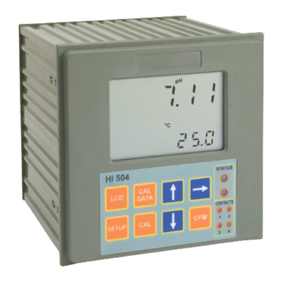
- Page 1 HI504 Panel-mounted, Microprocessor-based pH/ORP Process Controller Instruction Manual...
-
Page 2: Table Of Contents
TABLE OF CONTENTS WARRANTY . . . . . . . . . . . . . . . . . . . . . . . . . . . . . . . 3 MODEL IDENTIFICATION . -
Page 3: Warranty
WARRANTY HI504 is guaranteed for two years (sensors, electrodes and probes for six months) against defects in workmanship and materials when used for their intended purpose and main- tained according to instructions . This warranty is limited to repair or replacement free of charge . -
Page 4: Model Identification
Dear Customer, Thank you for choosing a Hanna Instruments Product . Please read this instruction manual carefully before using this instrument . This manual will provide you with the necessary information for the correct use of this instrument, as well as a precise idea of its versatility . -
Page 5: Preliminary Examination
. If there is any noticeable damage, please contact your local Hanna Instruments Office . Note Save all packing materials until you are sure that the instru- ment functions correctly . - Page 6 (either 7 .01 - 4 .01 - 10 .01 or 6 .86 - 4 .01 - 9 .18), or at 1 point with user-selectable value . • Temperature compensation of the Hanna Instruments Office standard buffers .
-
Page 7: Functional Description
FUNCTIONAL DESCRIPTION FRONT PANEL 1 . Liquid Crystal Display 2 . LCD key enters and exits the event scrolling mode . During pH calibration, alternately displays pH buffer value or current temperature 3 . SETUP key enters and exits setup mode 4 . - Page 8 REAR PANEL 1 . BNC Socket for pH or ORP electrode 2 . Connection for Potential Matching Pin 3 . Connection for electrode reference 4 . Connections for Pt 100/Pt 1000 temperature sensor 5 . Not Connected, for future use 6 .
-
Page 9: Specifications
SPECIFICATIONS -2 .00 to 16 .00 pH Range -2000 to 2000 mV -30 to 130 .0 ºC 0 .01 pH Resolution 1 mV 0 .1 ºC above -10 ºC; 1 ºC below ±0 .02 pH Accuracy ±2 mV (@25 °C/77 °F) ±0 .5 ºC (-9 .9 to 130 .0 ºC);... -
Page 10: Mechanical Dimensions
• 2 independent outputs Analog Output • 0 - 22 mA (configuring as 0-20 mA or 4-20 mA) Analog Output Resolution 0 .1‰ f .s . Analog Output Accuracy ± 2‰ f .s . Data logging 6000 pH/°C or ORP samples Environment 0 to 50 ºC;... -
Page 11: Installation
INSTALLATION Refer to diagram on page #9 • Input power: Connect a 3-wire power cable to the terminal strip line (L), earth (PE) and neutral (N) terminal connections . Power:100VAC-120mA / 115VAC-100mA / 230VAC- 50mA . Line Contact: 400mA fuse inside . PE must be connected to ground;... - Page 12 • Electrode: Connect the pH or ORP electrode to the BNC socket (#1 at page 9) . To benefit from the differential (symmetrical) input, con- nect the proper electrode wire (if available) or a cable with a potential matching pin (grounding bar) to the relevant terminal (#2 at page 9) and enable the differential input through the setup code I .04 .
-
Page 13: Calibration Mode
CALIBRATION MODE The calibration mode allows to calibrate the pH/ORP input, temperature input and 4-20 mA analog outputs . The controller is factory calibrated for all these parameters . Periodical calibration of the instrument is recommended, in particular when greatest accuracy is required and at least bi-yearly . - Page 14 The pH and ORP calibrations can not be initiated while the process controller is configurated to take measurements from the Digital Transmitter . pH CALIBRATION It is recommended to perform pH calibration when the probe is replaced and after any cleaning action . To perform any pH calibration procedure, the instrument has to be set as pH controller .
- Page 15 The default buffer set is the one used for last calibration, even if the procedure was not completed . • Once confirmed the set of buffer values, the primary LCD shows the measured pH value, while the sec- ondary LCD displays the first required buffer value .
- Page 16 • In the second case (pH value not close to the buffer) the meter will remain in the same state until the reading becomes unstable or the calibration mode is quitted . • For the second buffer value it is possible to choose be- tween pH4 .01 and pH10 .01 (or pH4 .01 and pH9 .18 if the NIST set has been selected) .
- Page 17 • The pH calibration value will switch to 7 .00, the first digit starts blinking and it is possible to change its value simply using the or key . • Once selected the first digit value, press the key: the first digit will be fixed and the second one will start blinking .
- Page 18 • When the reading becomes stable, if the ORP value is close to the calibration point, the “CFM” indicator starts blinking; otherwise the “WRONG” indicator blinks and the “CAL” is fixed on . • In the first case press CFM to confirm calibration . The meter will proceed showing the scrolling message “Press CFM again to confirm the current buffer or right to es- cape”...
- Page 19 • Once visualized the selected output, press the key to choose the range of the analog output (0-20 mA or 4-20 mA); then press the CFM key to confirm the choice . • Once selected and confirmed the range for the analog output, the secondary LCD shows the first point of calibration (1 or 4 mA) and the primary LCD displays the...
- Page 20 Note The instrument can support Pt100 or Pt1000 temperature sensor and calibration can be performed with anyone of these two probes . • After entering the calibration mode, move through the menu (using the or key) to choose the temperature and the correct kind of used probe;...
- Page 21 • When performing the second calibration point, it is pos- sible to choose between two values, 25 °C and 50 °C . Pressing the or key the value on the secondary LCD will switch between the two possibilities . •...
- Page 22 • In the first case press the CFM key to confirm calibration . The meter will proceed showing the scrolling message “Press CFM to confirm the current buffer or right to es- cape” (to prevent from confirming the calibration point inadvertently) .
-
Page 23: Setup Mode
SETUP MODE The Setup Mode allows the user to set all needed characteristics of the meter . To enter the mode, press the SETUP key and enter the password when the device is in idle or control mode . If the correct password is not entered, the user can only view the setup parameters (except for passwords) without modifying them (and the device remains in control mode) . - Page 24 • When the whole password has been inserted, press CFM to confirm it . Note The default password is set at “0000” . ENTERING SETUP ITEMS After confirmation of the password the primary LCD will show the name of the first setup group (see table) while the secondary LCD will display the setup code of the first item of the group .
- Page 25 Otherwise, if a numeric value has to be entered for the item, use the or key to change the value of the blinking digit and the key to cycle through the num- ber’s digits . • Once a value is set, press the CFM key to confirm . The instrument will turn to the next item and the new item’s value will be displayed on the primary LCD .
- Page 26 Note While in the setup mode, if no activity is performed for about 5 minutes after entering the setup mode, the mode is automatically exited and the instrument returns to the previous mode . The below table lists the setup codes along with the de- scription of the specific setup items, their valid values and whether the item is present for ORP mode .
- Page 27 Code Valid Values Default Present for ORP C .12 Hysteresis for setpoint 1 (H1) 0 .00 to 18 .00 pH or 1 pH or (see note 1) 0 to 4000 mV 50 mV C .13 Deviation for setpoint 1 (D1) 0 .50 to 18 .00 pH or 1 pH or (see note 1)
- Page 28 Code Valid Values Default Present for ORP C .53 Wednesday hold mode “OFF”: Disabled “OFF” enable “On”: Enabled C .54 Thursday hold mode enable “OFF”: Disabled “OFF” “On”: Enabled C .55 Friday hold mode enable “OFF”: Disabled “OFF” “On”: Enabled C .56 Saturday hold mode enable “OFF”: Disabled “OFF”...
- Page 29 Code Valid Values Default Present for ORP 0 .12 Measurement value for ana- -2 .00 to 16 .00 pH 0 .00 pH or log output 1 minimum or -2000 to 2000 mV -2000 mV (6) (0_VARMIN1) (0_VARMIN1 ≤ 0_VARMAX1-1 pH or 50 mV, 0_VARMIN1 ≤...
- Page 30 Code Valid Values Default Present for ORP 0 .31 Modem calls answer enable “OFF”: Disabled “OFF” (see note 20) “On”: Enabled 0 .32 Modem country code Dialing code of a country where “000” (see note 33) modem of HI504902 is certified INPUT (“InPU”) I .00 Measurement input selection “Prob”: BNC...
- Page 31 Code Valid Values Default Present for ORP P .03 Telephone number #2 00000000000000000000 to - - - - - - - - (see notes 20, 27) 99999999999999999999 - - - - - - - - (“- - - - - - - - - - - - - - - - - - - -” - - - - indicates no number) P .04 Number of remaining mes-...
- Page 32 Code Valid Values Default Present for ORP ADVANCED CLEANING (“ACLE”) L .10 Pre-rinsing time 0 to 99 s 20 s L .11 Detergent washing 0 to 99 s 10 s L .12 Rinsing time 5 to 99 s 20 s L .13 Pause time Min .
- Page 33 Code Valid Values Default Present for ORP E .14 Calibration time-out error 0 to 11 configuration and 24 to 35 (see note 7) E .20 Temperature broken probe 0 to 11 error configuration and 24 to 35 (see note 7) E .21 Temperature level error 0 to 5 configuration...
- Page 34 Notes (1): M1 can not be set to “OOHI” or “OOLO” if O .10 is set to “SEt” and vice versa; if M1 = “OOHI” then 16 .00 pH or 2000 mV S1+A1; if M1 = “OOLO” then -2 .00 pH or -2000 mV S1-A1;...
- Page 35 (3): When a wrong setup value is confirmed, the pH con- troller does not skip to the next setup item, but remains in the current item displaying a blinking “WRONG” indicator till the parameter value is changed by the user (the same thing happens also for the setup code selection) .
- Page 37 (8): The hold mode is never enabled by the control timing if the “hold time start” is the same as the “hold time end” . Items “C .41” and “C .42” apply to all days . The hold mode can be enabled all day by using items “C .51” through “C .57”...
- Page 38 (13): The alarm relay can be energized continuously (by se- lecting “LE” for “level”) or with a pulse (by selecting “PULS” for “pulse”) . The pulse length is fixed to about 5 seconds . (14): When the instrument is configured as ORP controller some of the above items or the item values are not anymore available to the user .
- Page 39 (22): Alarm relay delta value for setpoint 1 determines the value of the correspondent alarm threshold by being added to or subtracted from the setpoint value for a high (ON/ OFF or PID) or low (ON/OFF or PID) setpoint respectively . The same is true for Alarm relay delta value for setpoint 2 .
- Page 40 Taiwan, Turkey, United Kingdom, United States . If your country is not present in the list, please contact your local Hanna Instruments Office . If the country code is shorter than 3 characters, fill the code with zeros in front .
-
Page 41: Control Mode
CONTROL MODE The control mode is the normal operational mode for this meter . During control mode HI504 fulfills the following main tasks: • convert information from pH/ORP and temperature inputs to digital values and show them on the display;... - Page 42 In the first two cases the configuration of Setpoint (1 or 2) determines the operating mode of the relay . Once enabled, the control relay can be configured to control as a ON/ OFF or PID control of the acid/base dosage . A High-hight Alarm is imposed for acid/base dosage time when the relays are energized continuously .
- Page 43 As shown below, when the measured pH exceeds the set- point threshold, the relay(s) is (are) energized, until the pH measure falls below setpoint value minus hysteresis . Such a behavior is suitable to control an acid dosing pump . A relay enabled as a low setpoint, is energized when the pH value is below the setpoint and is de-energized when the pH value is above the sum of setpoint and the hysteresis .
- Page 44 The following graph describes the pH process controller behavior . Similar graph may apply to the mV controller . During proportional control the process controller calculates the relay activation time at certain moments t etc . The ON interval (the shaded areas) is then dependent to the error amplitude .
- Page 45 PID TRANSFER FUNCTION The transfer function of a PID control is as follows: Kp + Ki/s + s Kd = Kp(1 + 1/(s Ti) +s Td) with Ti = Kp/Ki, Td = Kd/Kp, where the first term represents the proportional action, the second is the integrative action and the third is the deriva- tive action .
- Page 46 . Many tuning procedures are available and can be applied to HI504 . A simple and profitable procedure is reported in this manual and can be used in almost all applications .
- Page 47 4 . The deviation, Ti and Td can be calculated from the fol- lowing: • Deviation = Tx * max . slope (pH or mV) • Ti = Tx / 0 .4 (minutes) • Td = Tx * 0 .4 (minutes) . 5 .
- Page 48 An hysteresis will eliminate the possibility of continuous sequences ‘energizing/de-energizing’ of the alarm relay when the measured value is close to the alarm setpoint . The hysteresis amplitude is 0 .2 pH for pH and 30 mV for ORP . Moreover the alarm signal is generated only after an user selectable time period (alarm mask) has elapsed since the controlled value has overtaken one alarm threshold .
- Page 49 This way, an alarm will warn the user when pH goes over the alarm thresholds, the power breaks down and in case of a broken wire between the process meter and the external alarm circuit . Note In order to have the Fail Safe feature activated, an external power supply has to be connected to the alarm device .
-
Page 50: In-Line Cleaning
IN-LINE CLEANING The cleaning feature allows an automatic cleaning action of the electrodes . To perform cleaning, the controller activates an external device (pump) . Cleaning can be of two types: • Simple cleaning: with water only, it can be triggered only by a timer (periodical cleaning) or by an error for which a cleaning action can be configured (i .e .a “Reference electrode broken or dirty”... - Page 51 • Rinsing time: the device enters hold mode; all relays configured for simple cleaning are energized . If the device is in normal measurement mode, the “rinSinG” message scrolls on the LCD; otherwise (i .e . the device is in setup mode) the cleaning is performed, but no message ap- pears .
- Page 52 If the “Repeated cleaning number” value (setup item L .16) is different from 0, then the advanced cleaning is repeated a number of times equal to this value after the first cycle (e .g . one more cycle if L .16=1) . Note If a cleaning session is being performed, it is possible to stop it by pressing and holding the ...
-
Page 53: Idle Mode
IDLE MODE During idle mode the device performs only measurements but it does not activate relays in order to control the process or let out a control signal to the analog output . In a normal situation the alarm relay is energized (no alarm condition) and the green LED is ON, the red LED is also fixed ON to warn users the device is not controlling the process, the yellow LEDs are OFF . -
Page 54: Hold Mode
HOLD MODE This function is started by: • calibration; • setup; • cleaning in place; • the hold digital insulated input when it is on; normally, the signal level is polled at least every 4 seconds; • the proper key combination ( and keys together) for service;... - Page 55 All the alarm signals (red LED, alarm relay, fault currents) are suspended while in hold mode (the correspondent er- ror events are not closed), unless the hold mode is being triggered by one or more errors and no other trigger source (different from an error) is active .
-
Page 56: Analog Output
ANALOG OUTPUT The meter is provided with two insulated current outputs . It is possible to configure the operating mode of each output through setup menu (items O .10 and O .20) . If the meter is configured as an ORP controller, the output #2 can be enabled to operate in control mode only (setup item O .20 set to “SEt”;... -
Page 57: Pc Communication
. It also has an on-line help feature to support you throughout the operation . The readings logged into the HI504 internal memory can be downloaded through HI92500 . HI92500 makes it possible for you to use the powerful means of the most diffused spreadsheet programs . - Page 58 (typically 120Ω) must be added at both ends of the line . The RS485 can connect up to 31 HI504 on the same physical network . All the units are slave devices and are monitored and controlled by a single master station (typi- cally an industrial PLC or PC) .
- Page 59 The process controller can only work as a slave component . In other words it can work as a remote terminal equipment answering to the commands only . RS485 PROTOCOL FOR HI504 Commands are composed of four parts: addresses, com- mand identifier, parameter, end of command .
- Page 60 Following is the complete list of commands available: Command Parameter Remarks NNMDR not available Requests firmware code (always available) NNHOP not available Requests hardware options NNSNR not available Requests hardware identifier (always available NNSTS not available Requests instrument status (relays, LEDs, configuration change flag, etc .) NNPHR not available...
- Page 61 Command Parameter Remarks NNHLD not available To enter/exit the hold mode (always available; pwd required) NNKDS null Same as LCD key NNKCD null Same as CAL DATA key NNKUP null Same as key NNKRG null Same as key NNKST null Same as SETUP key...
- Page 62 Blanks must be put on the tail for all items in order to have always a total length of 6 characters (see the setup table) . The same parameter format used for setup item set- ting is used also for setup item getting (i .e . when a “NNGETCNN<CR>”...
- Page 63 The time-out for the above answers is: 1) answer to “STS”, “PHR”, “MVR”, “TMR”, “AER” com- mands: 30 ms @ 19200 or 9600 bit/s, 40 ms @ 4800 bit/s, 60 ms @ 1200 bit/s (for the complete answer, from STX to ETX) . 2) answer to other commands: 2s (for the first character of the answer) .
- Page 64 The NNPHR, NNMVR, NNTMR requests produce the fol- lowing answer: “NN<STX><ASCII string for a float>S<ETX>” where S means “status” and can be equal to “A” (control and alarm ON), “C” (control ON and alarm OFF), “N” (control OFF) . The NNHOP request produces the following answer: “NN<STX>C <ETX>”...
- Page 65 The answer to the NNSTS command is: “NN<STX>C <ETX>” where C are the ASCII representation of byte B scribed below (e .g . B = 0xF3 = “F”, C = “3”), are the ASCII representation of byte B described below (e .g .
- Page 66 The NNCAR request produces the following answer: 1) Process controller configured for pH: If pH is not calibrated: “NN<STX>0<ETX>” If calibration has been performed: “NN<STX>1 date time offset slope1 slope2 buf1 buf2 N<ETX>” The items in italic are separated by blank spaces and have the following formats: date ddmmyy...
- Page 67 The event log file is requested through the NNEVF<CR> command . The maximum length of the event log file is 100 records . Here is the format for the answer: If there is no generated error or event, the answer has the format “NN<STX>0<ETX>”, otherwise: “NN<STX>events_no event_code start_date...
- Page 68 end_date (not active err .) ddmmyy (“020798” for July 2, 1998) end_time (active errors) (just the letter “N”) end_time (not active err .) hhmm (e .g . “0920” for 9:20 am) desA (errors) (just the letter “N”) desA (setup) (setup item format, prev . value) desA (calibration) “XXPHX”, “XOrPX”, “XX^CX”, “UOLtX”,...
- Page 69 “new_events_no” is the number of new events and its format is the ASCII format for a number (“1”, “2” ..“99”, “100”) . When a NNEVF<CR> or NNEVN<CR> command is received by the instrument, the new events list is reset and a following NNEVN<CR>...
- Page 70 bit 3 Digital transmitter error bit 4 Power reset bit 5 EEPROM corruption bit 6 Watchdog reset bit 7 Temperature level error bit 0 free for future use (and set to 0) bit 1 free for future use (and set to 0) bit 2 free for future use (and set to 0) bit 3...
-
Page 71: Short Messaging Service (Sms)
(or two) cellular phone(s) and through this feature the device can be monitored at every moment . Moreover if an error occurs on the HI504, it is possible to have an SMS sent to the cellular phone(s) advising immediately the user about the problem . - Page 72 By pressing the key, the first digit will be fixed on and it will be possible to select the next digit . When the fourth digit is reached, by pressing the key again, the number on the primary display will scroll of one position to the left and the fifth digit of the phone number will be shown on the fourth position .
- Page 73 When the desired phone number is entered, press CFM to confirm . The WRONG tag will blink if the user tries to confirm an incorrect number (the first digit of the number has to be on the first position and the “-” character have not to be present in the middle of the number) .
- Page 74 “Rem_msg: xxx; The following error oc- curred on HI504: XXXXX” . “xxx” stands for a three digits number indicating the remain- ing messages; “XXXXX” stands for a text string correspondent...
- Page 75 . The phone call advises the user that something happened on the HI504 and a SMS is going to be received . It is not necessary for the user to answer the phone call and it is suggested to close it without any answer .
- Page 76 The P .05 item sets the number of repeated messages to send (0 is associated with no repetition: only one warning message will be sent and no confirmation waited), while the P .06 item sets the delay (in minutes) between two sub- sequent messages .
- Page 77 (the lower limit depends on the value of item P .05), the message “Rem_msg: xxx; Maximum number of Sms reached . Please check the HI504 SIM card charge level” will be sent by the instrument to the programmed phone number(s) .
- Page 78 P .02 (and P .03) . This is accomplished by sending to the instrument the SMS “+Pxx”, where “xx” indicates the ID of the HI504 (setup item G .11) . The instrument will recognize the command and reply send- ing the requested information .
-
Page 79: Modem Connection
A SIM card able to receive data calls must be used . •Over a standard analog telephone line, connecting the HI504902 modem module to HI504 RS485 port . To enable the modem connection with HI504902, first set item P .00 to “PC”, then set item O .31 to “On” and finally set item O .32 with the dialing code of the country where... - Page 80 • set P .00 to “CELL” in more than one device in the same RS485 network (SMSs can not be sent from more than one HI504); • set O .31 to “On” in one device and P .00 to “CELL” in another one within the same RS485 network;...
- Page 81 When a modem connection is up, the cellular module does not send any SMS . If an error for which the SMS sending is enabled is active after closing the modem connection, an alarm SMS will be sent by the HI504 after disconnection .
-
Page 82: Ph/Orp Probe Check
PROBE CHECK The pH electrode and the reference electrode for both pH and ORP can be automatically monitored through HI504 . Setup items involved are I .13 (pH electrode impedance test enable), I .14 (reference electrode impedance test enable), I .15 (maximum reference electrode impedance) and I .04... -
Page 83: Solution Compensation
(due to the chemical properties of the solution); if the same solution compensa- tion formula is applied in both HI504 and the reference pH-meter, they will read the same value . To enable the solution compensation, set the S .00 item in the setup menu to “ON”... -
Page 84: Temperature Compensation
TEMPERATURE COMPENSATION If the setup item G .01 is set to “AtC” an automatic tempera- ture compensation will be performed using the temperature value acquired with the Pt100/Pt1000 input . If the probe appears to be unconnected, or anyway it does not give a valid temperature (temperature outside the -30 to 130 °C range), the instrument will generate a broken temperature probe error, which will be handled as stated... - Page 85 For quickly changing the temperature value press and hold down the (or ) key: the temperature will be incremented (decremented) of 0 .1 °C until the total amount is 0 .4 °C, and then the increment (decrement) will turn to 1 °C . During these operations both the temperature value dis- played and setup item G .02 are updated (the last one is updated with a maximum delay of 10s) .
-
Page 86: Last Calibration Data
LAST CALIBRATION DATA If the meter is set as pH controller, the following data about the last calibration are stored in the EEPROM: • Date • time • offset, in mV • slope, in mV/pH • up to two buffers . If the meter is set as ORP controller, the data stored in the EEPROM are the following: •... - Page 87 Pressing the key, the meter will cycle through the follow- ing steps in reverse order, i .e . beginning from last buffer . Note At any time pressing LCD or CAL DATA key the meter will return to the regular operating display . •...
-
Page 88: Offset And Slope Direct Selection
OFFSET AND SLOPE DIRECT SELECTION It is possible to edit directly the values of the offset and the slope to calibrate the instrument . • Press the CAL DATA key entering the last calibration data scrolling and then press the SETUP key . •... - Page 89 • If an offset calibration has been made, the instrument will turn to “slope” calibration (as indicated by the “SLO” message on the secondary display . The slope value is shown on the primary LCD and the first digit is blinking to permit modifications) .
-
Page 90: Event Log File Scrolling
EVENT LOG FILE SCROLLING The event log file is composed by a maximum of 100 recorded events, which include errors, calibration events (type of calibration, date, time), configuration changes and cleaning events (type of cleaning, start date and time) . To enter the event log file scrolling, press the LCD key while in control, hold or idle mode (the log feature is not avail- able in setup or calibration mode) . - Page 91 • for cleaning events: • start date • start time • type of cleaning (“AdCL” for advanced cleaning; “SICL” for simple cleaning) . Once entered the log event scrolling, press the or key to move through the events . If the event is an error still active, the error code on the primary LCD will blink, otherwise it will be fixed .
-
Page 92: Fault Conditions
FAULT CONDITIONS The below fault conditions may be detected by the software: • EEPROM data error • serial communication internal bus failure • software dead loop . EEPROM data error can be detected through EEPROM test procedure at start-up or when explicitly requested us- ing setup menu, or during normal operational mode if a checksum control fails . - Page 93 If the error is due to impossible communication with the EEPROM or the RTC, all the pH/ORP controller tasks are stopped, the alarm relay is de-energized, the red LED blinks and the “Serial bus error” slides forever (repair can not be postponed) .
-
Page 94: Selftest Procedures
SELFTEST PROCEDURES The selftest procedure can be made only entering the setup menu and selecting one of the items of the “tESt” group (t .00 - t .08) . Note All the tests are made while in setup mode, where a time-out is present . - Page 95 KEYBOARD TEST • To enter the keyboard test procedure select setup item t .01 . A blinking “OFF” message will appear on the pri- mary LCD . • Press the (or ) key once and the message will switch to a blinking “GO”...
- Page 96 For example, if SETUP and keys are pressed together the LCD will look like this: Note A maximum of two keys may be pressed simultaneously to be properly recognized . •To exit the keyboard test procedure press LCD, CAL and SETUP simultaneously;...
- Page 97 • During this time the instrument performs the EEPROM check, and if the checksum is correct, the “Stored data good” message will scroll on the primary display . • After that, the meter will remain in setup menu and move to the next setup item .
- Page 98 • Some keys are used to toggle relays and LEDs ON and OFF: - the LCD key toggles the alarm relay and the alarm LED; - the CAL DATA key toggles the red LED; - the key toggles relay 1 and the corresponding LED; - the ...
- Page 99 This value is let out to the analog output and coincides with the minimum value of the analog output type cho- sen with setup item O .11 (analog output 1) and O .21 (analog output 2) . • A new output value can be edited manually . It is possible to change the value of the first blinking digit by pressing the ...
- Page 100 • Press CFM key to confirm or the (or ) key again to return to the previous status . • If confirmation is given when the “OFF” message is blink- ing, no action is performed and it will move to the next setup item (t .07) .
- Page 101 •To exit the test press the CFM key; the instrument will remain in the setup menu and move to the next setup item (t .08) . Note During the test the relays are activated, the primary LCD will always show the “ACLE” message and on the secondary display will be shown the actual status of the digital input (“On”...
-
Page 102: Alarm - Error Configuration
ALARM - ERROR CONFIGURATION This section is dedicated to all the possible error causes for alarm generation, and to the actions performed according to the alarm configuration (setup menu “Error configura- tion”) . Each alarm cause can be referred to an error to which an error code is assigned and which is logged in a dedicated memory space (see “Event logging”... - Page 103 (*): When the Digital Transmitter is used, these errors are generated in the Digital Transmitter, but they are handled as if they were generated in the Process Controller . • If the condition to generate a “Reference electrode broken or dirty” error is met, the error is not generated immedi- ately, but first auto-cleaning is performed up to 2 times (the cleaning type depends upon relays configuration) .
- Page 104 • The “Cellular error” is never activated if the serial lines are not configured for cellular module connection . The error will be active if the instrument is not able to com- municate with the cellular engine (for example because the serial cable is broken or because the cellular engine is not powered), if the number of available SMS is finished (menu item P .04) or if the SIM expiration date is overrun .
-
Page 105: Ph Values At Various Temperatures
pH VALUES AT VARIOUS TEMPERATURES Temperature has a significant effect on pH . The calibration buffer solutions are effected by temperature changes to a lesser degree than normal solutions . For manual temperature calibration please refer to the following chart: TEMP pH VALUES °C... -
Page 106: Electrode Conditioning And Maintenane
ELECTRODE CONDITIONING AND MAINTENANCE PREPARATION Remove the electrode protective cap . DO NOT BE ALARMED IF ANY SALT DEPOSITS ARE PRES- ENT . This is normal with electrodes and they will disappear when rinsed with water . During transport tiny bubbles of air may have formed in- side the glass bulb . - Page 107 . • Drifting: soak the electrode tip in warm Hanna Instruments Office Solution HI7082 for one hour and rinse tip with distilled water .
- Page 108 • No Slope: - Check the electrode for cracks in glass stem or bulb (replace the electrode if cracks are found) . - Make sure cable and connections are not damaged nor lying in a pool of water or solution . •...
-
Page 109: Definitions
DEFINITIONS DEVIATION Same as proportional band, but expressed in units of the controlled magnitude (e .g . 1pH, 50 mV) . EEPROM Electrically Erasable Programmable Read-only Memory (permanent memory) . FAIL SAFE ALARM Signaling of the alarm by de-energizing the alarm relay instead of energizing it . -
Page 110: Accessories
Inorganic Cleaning Solution, 230 or 500 ml bottle HI7077M or HI7077L Oil & Fat Cleaning Solution, 230 or 500 ml bottle OTHER ACCESSORIES HI504900 Hanna Instruments Office GSM Module HI504901 Hanna Instruments Office GSM Supervisor HI504902 Hanna Instruments Office RS485 Modem... - Page 111 HI7611 Stainless steel Pt1000 probe with standard 1/2’’ external threads on both ends for in-line and immersion installation; 5 m (16 .5’) cable HI7621 Glass Pt1000 probe with external PG13 .5 thread and 5 m (16 .5’) cable HI60542-0 1 set of O-rings for HI60542 electrode holder HI60545-0 1 set of O-rings for HI60545 electrode holder HI60501-0...
- Page 112 pH AND ORP ELECTRODE HOLDERS HI60542 In-line electrode holder for direct pipe installation HI60545 Bypass loop electrode holder...
- Page 113 HI60501 Immersion electrode holder for tanks, vessels, baths and open channels Specifications HI60542 HI60545 HI60501 Electrode Holder Material PVC O-Ring Material Min . & Max . Temperature -10 °C (14 °F) & 60 °C (144 °F) Min . Immersion Length 10 cm (3 .9’’) Max .
- Page 114 . For a complete list of available electrodes visit our web site at www.hannainst.com or contact your local Hanna Instruments Office . The below table lists all the Combination, Flat tip, PVDF-body, polymer filled electrodes...
- Page 115 Recommendations for Users Before using these products, make sure that they are entirely suitable for the environment in which they are used . Operation of these instruments in residential areas could cause unacceptable interferences to radio and TV equipment . To maintain the EMC performance of equipment, the recommended cables noted in the user’s manual must be used .
- Page 116 Hanna Instruments Inc. Highland Industrial Park 584 Park East Drive Woonsocket, RI 02895 USA Technical Support for Customers Tel . (800) 426 6287 Fax (401) 765 7575 E-mail tech@hannainst .com www .hannainst .com MAN504 10/17 Printed in ROMANIA...
Need help?
Do you have a question about the HI504 and is the answer not in the manual?
Questions and answers
ORP METER PANAL MOUNTED DATA SHEET