
Related Manuals for Hanna Instruments HI510


Summary of Contents for Hanna Instruments HI510
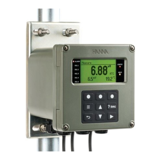
- Page 1 INSTRUCTION MANUAL HI510 HI520 Universal Process Controller Modbus RTU Protocol and Remote Device Control Hanna Instruments Inc., 584 Park East Drive, Woonsocket, RI 02895 USA www.hannainst.com...
- Page 2 All rights are reserved. Reproduction in whole or in part is prohibited without the written consent of the copyright owner, Hanna Instruments Inc., Woonsocket, Rhode Island, 02895, USA. Hanna Instruments reserves the right to modify the design, construction, or appearance of its products without advance notice.
-
Page 3: Table Of Contents
Certification ................................48 Recommendations for Users ............................48 Warranty ..................................48 General Safety Precautions & Installation Recommendations HI510 HI520 safety precautions and installation recommendations apply. Procedures and instructions detailed in this section may require special precautions to ensure the safety of the personnel performing the operations. -
Page 4: Introduction
Introduction 1. INTRODUCTION Modbus is a request‑response software protocol intended for efficient and immediate remote industrial process control. Main Features • Allows immediate response to a problem with equipment (even from different plants) • Minimizes production downtime as mechanical issues are quickly identified •... - Page 5 Modbus Protocol Basics General query message structure Device Address Function Code Query Data Error Check Error Check Response Data Function Code Device Address • Device Address – individual client address • Function Code – type of action • Query Data Response Data –...
- Page 6 Modbus Protocol Basics Modbus Functions Modbus data types • Coil (1 bit), read/write access, address range 9999 – forces the ON/OFF state of discrete outputs (DO) or modifies mode / status of client devices • Discrete Input (1 bit), read‑only, 10001 19999 address range...
- Page 7 Modbus Protocol Basics Read Coils (0x01) Read from 1 to 2000 maximum contiguous status of coils Request Function code 1 byte 0x01 Starting address 2 bytes 0x0000 to 0xFFFF 0 to 65535 Quantity of coils 2 bytes 0x0001 to 0x07D0 1 to 2000 Normal Function code...
- Page 8 Modbus Protocol Basics Write Single Coil (0x05) Write a single output to either ON or OFF Request Function code 1 byte 0x05 Coil address 2 bytes 0x0000 to 0xFFFF 0 to 65535 Coil value 2 bytes 0x0000 or 0xFF00 0 or 65280 Normal Function code 1 byte...
- Page 9 = Object ID 0x81 = Conformity Level 0x00 = More Follows (NO) 0x00 = Next Object ID (None) 0x01 = Number of Objects object) 0x00 = Object ID (Vendor Name) 0x11 = Object Length characters) "Hanna Instruments" = Object Value...
-
Page 10: Wiring & Settings Configuration
• Press Setup to configure Communication Protocol parameters (to match the Modbus server). Setup Enable 3.2.1. Configurable parameters Remote Control Option: Enabled, Disabled Option must be enabled when using the Modbus protocol. The check mark confirms the option as enabled Н or disabled М. HI510 HI520... - Page 11 Й remote connection to a Modbus server established Л remote connection to a Modbus server established (controller operating in editing mode) Measure ORP pH & ORP °C 6.43 25.0 HI510 HI520 °C °C 25.0 25.0 Comm Protocol (Communication Protocol) Parameter indicates supported transmission mode (Modbus RTU).
- Page 12 Wiring & Settings Configuration Parity: sets communication parity based on the parity mode of the connected device. • With item selected, press Modify for the drop‑down list to display. • Press the keys to navigate between options. Press Select to save. Stop Bits: sets stop bit option based on the stop bit of the connected device.
-
Page 13: Operation Modes When Using Modbus
Operation Modes when Using Modbus 4. OPERATION MODES WHEN USING MODBUS Mode Type Scope Description Manual Local control, controller Controller operated manually. operated manually Note: Remote Control is not available. Local Edit Local edit of Local edit of controller’s settings and parameters. settings &... -
Page 14: Modbus Special Holding Registers
Operation Modes when Using Modbus 4. Send a 32‑bit password to the controller using 2 consecutive Write Single Holding Register (06) Modbus Function Codes or a single Write Multiple Holding Registers (16) Function Code to the controller. The password register addresses are: •... -
Page 15: Editing & Saving Controller Parameters
Operation Modes when Using Modbus 4. Use Read Coil (01), Read Input (02), Read Holding Register (03), or Read Input Register (04) function codes to read parameter values off the controller. See Modbus Functions for register details. 5. Repeat step 4 as needed. ` Modbus Exception Codes may be encountered. -
Page 16: Modbus Functions
Controller’s parameters can be read or modified via Modbus functions. Parameters are grouped based on their function. Not all addresses are used; unused addresses are not shown. 5.1. SUPPORTED FUNCTION CODES HI510 HI520 support following standard Modbus function codes: Decimal... -
Page 17: Coil Registers Functions (0Xxxx Addresses)
00040 Math CH, enable Alarm3 _ Low enable Alarm Low Note: Channel 2 (CH2)/Math Channel (Math CH) addresses do not apply to HI510. Readings related to CH2/Math CH address items are routed as requests to the corresponding CH1 address item. -
Page 18: Discrete Inputs Functions (1Xxxx Addresses)
10082 Math CH Alarm Low Status 10049 CH1 Setpoint 1, Overtime Alarm Note: Channel 2 (CH2)/Math Channel (Math CH) addresses do not apply to HI510. Readings related to CH2/Math CH address items are routed as requests to the corresponding CH1 address item. -
Page 19: Input Registers Functions (3Xxxx Addresses)
Modbus Functions 5.5. INPUT REGISTERS FUNCTIONS (3XXXX ADDRESSES) Decimal Name 0x04 Read Input Register Address Parameter Size Note Reserved 512 bytes Reserved for internal use, 30501 not related to controller status and settings. Controller Serial Number 12 bytes bytes 1‑0 30513 bytes 3‑2... - Page 20 Modbus Functions Address Parameter Size Note CH1 Main Parameter Value float Low part of float (bytes 1‑0) 30545 High part of float (bytes 3‑2) 30546 CH1 Main Parameter Engineering Unit 8 bytes bytes 1‑0 30547 bytes 3‑2 30548 bytes 5‑4 30549 bytes 7‑6...
- Page 21 Modbus Functions Address Parameter Size Note uint8 _ t CH1 Aux. 1 Parameter Measure Status bit 0 = Measure Stable 30571 bit 1 = Measure Underrange bit 2 = Measure Overrange bit 3 = Sensor Broke bit 4 = Measurement Out of Calibration Range bit 5 = Measurement stays on a...
- Page 22 Modbus Functions Address Parameter Size Note CH2 Temperature Parameter Value float Low part of float (bytes 1‑0) 30594 High part of float (bytes 3‑2) 30595 CH2 Temperature Parameter Engineering Unit 8 bytes bytes 1‑0 30596 bytes 3‑2 30597 bytes 5‑4 30598 bytes 7‑6...
- Page 23 Modbus Functions Address Parameter Size Note uint8 _ t CH1 Probe Model = pH probe 30641 CH1 Probe Code 14 bytes bytes 1‑0 30642 bytes 3‑2 30643 bytes 5‑4 30644 bytes 7‑6 30645 bytes 9‑8 30646 bytes 11‑10 30647 bytes 13‑12 30648 uint8 _ t...
- Page 24 Modbus Functions Address Parameter Size Note CH1 Temperature Parameter High Limit Value float Low part of float (bytes 1‑0) 30688 High part of float (bytes 3‑2) 30689 uint8 _ t CH1 Temperature Parameter Limits Resolution 30690 CH1 Aux. 1 Parameter Name 8 bytes bytes 1‑0...
- Page 25 Modbus Functions Address Parameter Size Note CH2 Probe FW Version 7 bytes bytes 1‑0 30736 bytes 3‑2 30737 bytes 5‑4 30738 Byte 30739 uint8 _ t CH2 Probe Measure Mode 30740 uint8 _ t CH2 Probe Measure Unit 30741 CH2 Main Parameter Name 8 bytes bytes 1‑0...
- Page 26 Modbus Functions Address Parameter Size Note uint8 _ t CH2 Aux. 1 Parameter Limits Resolution 30783 CH2 Aux. 2 Parameter Name 8 bytes bytes 1‑0 30784 bytes 3‑2 30785 bytes 5‑4 30786 bytes 7‑6 30787 CH2 Aux. 2 Parameter Engineering Unit Basic Name 8 bytes bytes 1‑0...
- Page 27 Modbus Functions Address Parameter Size Note = EC Temperature Compensation Mode • Linear • Natural • Standard • None uint8 _ t CH1 Probe Constant1 Resolution {0,1,2,3} 30802 uint8 _ t CH1 Probe Constant1 Type 30803 = Incremental Type = Unit Type = Check Glass Impedance = Check Reference Impedance = Temperature Compensation Type...
- Page 28 Modbus Functions Address Parameter Size Note uint8 _ t CH1 Probe Constant3 Resolution 30832 uint8 _ t CH1 Probe Constant3 Type 30833 CH1 Probe Constant3 Name 24 bytes bytes 1‑0 30834 bytes 3‑2 30835 bytes 5‑4 30836 bytes 7‑6 30837 bytes 9‑8 30838...
- Page 29 Modbus Functions Address Parameter Size Note uint16 _ t CH1 Probe Constant6 Value 30876 uint8 _ t CH1 Probe Constant6 Resolution 30877 uint8 _ t CH1 Probe Constant6 Type 30878 CH1 Probe Constant6 Name 24 bytes bytes 1‑0 30879 bytes 3‑2 30880 bytes...
- Page 30 Modbus Functions Address Parameter Size Note bytes 21‑20 30919 bytes 23‑22 30920 uint16 _ t CH1 Probe Constant9 Value 30921 uint8 _ t CH1 Probe Constant9 Resolution 30922 uint8 _ t CH1 Probe Constant9 Type 30923 CH1 Probe Constant9 Name 24 bytes bytes 1‑0 30924...
- Page 31 Modbus Functions Address Parameter Size Note = Check Reference Impedance = Temperature Compensation (–Min. Range Value ÷ Max. Range Value) = Manual Temperature Compensation (–Min. Range Value ÷ Max. Range Value) = Temperature Offset (–Min. Range Value ÷ Max. Range Value) = Calibration Timeout (–Min.
- Page 32 Modbus Functions Address Parameter Size Note uint16 _ t CH2 Probe Constant1 Value 30985 = Incremental (–Min. Range Value ÷ Max. Range Value) = Unit DO probe • DO saturation (%DO) 0 or 1 • DO concentration (mg/L) • DO concentration (ppm) EC probe •...
- Page 33 Modbus Functions Address Parameter Size Note = Incremental Calibration Timeout 30987 = Incremental Resolution Type = Incremental Buffer Type = Meter Mode = Parameter Source = EC Temperature Compensation Type CH2 Probe Constant1 Name 24 bytes bytes 1‑0 30988 bytes 3‑2 30989 bytes...
- Page 34 Modbus Functions Address Parameter Size Note bytes 17‑16 31026 bytes 19‑18 31027 bytes 21‑20 31028 bytes 23‑22 31029 uint16 _ t CH2 Probe Constant4 Value 31030 uint8 _ t CH2 Probe Constant4 Resolution 31031 uint8 _ t CH2 Probe Constant4 Type 31032 CH2 Probe Constant4 Name 24 bytes bytes...
- Page 35 Modbus Functions Address Parameter Size Note bytes 15‑14 31070 bytes 17‑16 31071 bytes 19‑18 31072 bytes 21‑20 31073 bytes 23‑22 31074 uint16 _ t CH2 Probe Constant7 Value 31075 uint8 _ t CH2 Probe Constant7 Resolution 31076 uint8 _ t CH2 Probe Constant7 Type 31077 CH2 Probe Constant7 Name...
- Page 36 Modbus Functions Address Parameter Size Note bytes 13‑12 31114 bytes 15‑14 31115 bytes 17‑16 31116 bytes 19‑18 31117 bytes 21‑20 31118 bytes 23‑22 31119 uint16 _ t CH2 Probe Constant10 Value 31120 uint8 _ t CH2 Probe Constant10 Resolution 31121 uint8 _ t CH2 Probe Constant10 Type 31122...
- Page 37 23‑22 31149 Note: Channel 2 (CH2)/Math Channel (Math CH) addresses do not apply to HI510. Readings related to CH2/Math CH address items are routed as requests to the corresponding CH1 address item. Writing to CH2/Math CH address items generates a response error.
-
Page 38: Holding Registers Functions (4Xxxx Addresses)
Modbus Functions 5.6. HOLDING REGISTERS FUNCTIONS (4XXXX ADDRESSES) Decimal Name 0x03 Read Holding Register 0x06 Write Single Holding Register 0x10 Write Multiple Holding Registers Min. Max. Default Address Register Function Size Details Value Value Value uint32 _ t Low part of uint32 _ t 40001 Remote Password (bytes 1‑0) High part of uint32 _ t... - Page 39 Modbus Functions Min. Max. Default Address Register Function Size Details Value Value Value uint8 _ t 40017 Communication Protocol – = Modbus RTU uint8 _ t 40018 Bus Address uint8 _ t 40019 Baud Rate = 9K6 = 19K2 = 38K4 = 57K6 = 115K2 = 256K0...
- Page 40 Modbus Functions Min. Max. Default Address Register Function Size Details Value Value Value uint8 _ t 40049 Cleaning Schedule Saturday uint8 _ t 40050 Cleaning Schedule Sunday uint8 _ t 40051 Input1 Function = Disabled = Hold = Clean uint8 _ t 40052 Input1 Active Level = Low = High...
- Page 41 Modbus Functions Min. Max. Default Address Register Function Size Details Value Value Value uint8 _ t 40077 AO2 Parameter to Follow = Ctrl SetP1 = Ctrl SetP2 = Main parameter = Temp. Param. = Auxiliary Param. uint8 _ t 40078 AO2 mA Range = “0‑20 mA”...
- Page 42 Modbus Functions Min. Max. Default Address Register Function Size Details Value Value Value uint8 _ t 40099 AO4 Mode = Disabled = Track Channel uint8 _ t 40100 AO4 Data Channel = CH1 (Probe 1) = CH2 (Probe 2) uint8 _ t 40101 AO4 Parameter to Follow = Ctrl SetP1 = Ctrl SetP2...
- Page 43 Modbus Functions Min. Max. Default Address Register Function Size Details Value Value Value uint8 _ t 40136 CH1 Setpoint 1 Control Action = Low direction = High direction uint16 _ t 40137 CH1 Setpoint 1 Control Period 1800 [seconds] 40138 CH1 Setpoint 1 Deviation float Parameter Parameter...
- Page 44 Modbus Functions Min. Max. Default Address Register Function Size Details Value Value Value 40165 CH1 Main Param. Alarm High Value float Param. low Param. high Param. dep. Low part of float limit measured limit measured default (bytes 1‑0) 40166 High part of float (bytes 3‑2) 40167 CH1 Main Param.
- Page 45 Modbus Functions Min. Max. Default Address Register Function Size Details Value Value Value 40197 High part of float (bytes 3‑2) uint16 _ t 40198 CH2 Setpoint 1 Reset Time 60000 60000 [seconds] uint16 _ t 40199 CH2 Setpoint 1 Rate Time 60000 [seconds] uint8 _ t...
- Page 46 Modbus Functions Min. Max. Default Address Register Function Size Details Value Value Value uint8 _ t 40225 CH2 Temp. Param. Alarm High Enable = Disable = Enable uint8 _ t 40226 CH2 Temp. Param. Alarm Low Enable = Disable = Enable uint16 _ t 40227 CH2 Temp.
-
Page 47: Abbreviations
40273 Math CH Alarm3 Delay Off Time [seconds] Note: Channel 2 (CH2)/Math Channel (Math CH) addresses do not apply to HI510. Readings related to CH2/Math CH address items are routed as requests to the corresponding CH1 address item. Writing to CH2/Math CH address items generates a response error. -
Page 48: Certification
If the repair is not covered by the warranty, you will be notified of the charges incurred. If the instrument is to be returned to Hanna Instruments, first obtain a Returned Goods Authorization (RGA) number from the Technical Service department and then send it with shipping costs prepaid.
Need help?
Do you have a question about the HI510 and is the answer not in the manual?
Questions and answers