
Subscribe to Our Youtube Channel
Related Manuals for Hanna Instruments HI9910


Summary of Contents for Hanna Instruments HI9910
- Page 1 Instruction Manual HI9910 • HI9911 HI9920 Wall Mounted pH & ORP Controllers w w w . h a n n a i n s t . c o m...
-
Page 2: Table Of Contents
This warranty is limited to free of charge repair or replacement of the meter only, if any malfunctioning is due to manufacturing defects. If service is required, contact your local Hanna Instruments Office. If under warranty, report the model number, date of purchase, serial number and the nature of the problem. -
Page 3: Preliminary Examination
2 A fuses. Use only the specified fuses for replacement. GENERAL DESCRIPTION HI9910, HI9911 and HI9920 are wall-mounted pH and ORP regulators designed to meet a variety of process control requirements. The electrode can be installed by simply plugging it to the universal BNC socket on the bottom of the meter. -
Page 4: Mechanical Layouts
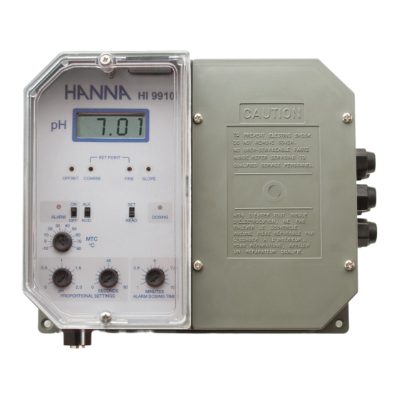
MECHANICAL LAYOUTS Fig.1 Figure 1: BNC plug for electrode and wiring access ports. Fig.2 Figure 2: Controls and terminals of the HI9910 pH controller. Layouts vary according to model. Fig.3 Figure 3: Dimensioned bottom view. - Page 5 Fig.4 Figure 4: Dimensioned front view. The molded, mounting holes in the four corners provide for quick and secure installation. No additional hardware is needed for mounting. All electri- cal connections and controls are located on the front of the instrument, so that any adjustment can be made without needing to remove the unit.
-
Page 6: Hi9910 Functional Description & Specifications
HI9910 FUNCTIONAL DESCRIPTION 1. Liquid Crystal Display 2. Slope calibration trimmer 3. Setpoint trimmer for Fine adjustment 4. Setpoint trimmer for Coarse adjustment 5. Offset calibration trimmer 6. Dosing LED 7. READ/SET switch for selecting normal measurement or setpoint adjustment mode 8. - Page 7 -10 to 50 °C (14 to 122 °F); ENVIRONMENT RH 95% non-condensing CASE MATERIAL Fiber-reinforced, flame-retardant ABS HI9910-1 : 115 Vac, 60 Hz POWER SUPPLY HI9910-2 : 230 Vac, 50 Hz HI9910-3 : 100 Vac, 50/60 Hz ENCLOSURE 181 x 221 x 142 mm (7.1 x 8.7 x 5.6”) 1.6 kg (3.5 lb.)
-
Page 8: Hi9911 Functional Description & Specifications
HI9911 FUNCTIONAL DESCRIPTION 1. Liquid Crystal Display 2. Slope calibration trimmer 3. Setpoint trimmers for acid and alkaline feed, Fine tuning 4. Setpoint trimmers for acid and alkaline feed, Coarse adjustment 5. Offset calibration trimmer 6. Dosing LED’s for acid and alkaline feed 7. - Page 9 HI9911 SPECIFICATIONS RANGE 0.00 to 14.00 pH RESOLUTION 0.01 pH ACCURACY ±0.02 pH (@25 °C/77 °F) TYPICAL EMC DEV. ±0.1 pH User-selectable, 0-20 mA or 4-20 mA mA OUTPUT over the 0-14 pH range with isolated output Through “OFFSET” and “SLOPE” trimmers CALIBRATION (Max.
-
Page 10: Hi9920 Functional Description & Specifications
HI9920 FUNCTIONAL DESCRIPTION 1. Liquid Crystal Display 2. Setpoint trimmer for Fine adjustment 3. Setpoint trimmer for Coarse adjustment 4. Calibration trimmer 5. Dosing LED 6. READ/SET switch for selecting normal measurement or setpoint adjustment mode 7. Oxidization/Reduction Dosage selection switch 8. - Page 11 HI9920 SPECIFICATIONS RANGE -500 to 1500 mV RESOLUTION 1 mV ACCURACY ±5 mV (@25 °C/77 °F) TYPICAL EMC DEV. ±6 mV User-selectable, 0-20 mA or 4-20 mA mA OUTPUT over the -500 to 1500 mV range with isolated output CALIBRATION Through “CAL”...
-
Page 12: Connections & Wiring
RELAY CONNECTIONS • Wire the external device(s), as pump or electrovalve, directly to the relay terminal strip (one for HI9910 and HI9920, and two for HI9911) of the controller. The terminals are powered and no external power supply for pump or electrovalve is needed. - Page 13 ALARM CONNECTIONS • The alarm threshold is user-selectable from 0.5 to 2.5 pH for HI9910 and HI9911, or from 50 to 250 mV for HI9920, by turning the alarm trimmer with a small screwdriver. If the actual measurement is above or below the setpoint by a value greater than the selected threshold, the alarm terminal is activated.
- Page 14 • The alarm is activated for readings varying as follow: HI9910: 0.5 to 2.5 pH (user-selectable) above or below the setpoint; HI9911: 0.5 to 2.5 pH (user-selectable) lower than the ALKALINE setpoint or higher than the ACID setpoint; HI9920: 50 to 250 mV (user-selectable) above or below the setpoint.
- Page 15 For solutions not compatible with stainless steel, use the HI7620 glass- body probe, or another appropriate 3-wire Pt100 probe. MAIN POWER SUPPLY CONNECTION • For each model (HI9910, HI9911, HI9920) three versions are available, according to different power supply requirement: version -1 works at 115 Vac; 60 Hz version -2 works at 230 Vac;...
-
Page 16: Ph Calibration
CALIBRATION (HI9910 and HI9911) Properly connect the pH electrode and wire the separate ground probe (if used) to the controller, then plug the meter to the mains. It is recommended to perform calibration at a temperature similar to that of the sample to be monitored. - Page 17 • Wait for the reading to stabilize and then adjust the “OFFSET” trimmer to display the buffer pH value at the measured temperature, e.g. pH7.01 if the temperature is 25 °C (77 °F). • Refer to the table at page 25 for the appropriate buffer value at a given temperature, and adjust the trimmer accordingly.
-
Page 18: Orp Calibration
ORP CALIBRATION (HI9920) Properly connect the ORP electrode and wire the separate ground probe (if used) to the controller, then plug the meter to the mains. Remove the electrode protective cap. Immerse the electrode and the ground probe (if in use) in the reference solution. An immersion level of about 4 cm (1.5”) is recommended. -
Page 19: Setpoint Adjustment
SETPOINT ADJUSTMENT The electrode and the ground probe (if in use) have to be properly installed and calibration performed. FOR HI9910 Set the SET/READ switch to “SET” posi- tion; the display shows the previously set value (e.g. pH8.00). Using a small screwdriver, first adjust the value through the COARSE trimmer and then tune it through the FINE trimmer until the desired setpoint value is displayed (e.g. - Page 20 FOR HI9911 (DUAL-POINT ADJUSTMENT) a) ACID SETPOINT and DOSAGE To set the upper limit and direct the controller to lower the pH value, set the SET/READ switch to “SET” and the ALK/ACID switch to “ACID”; the display shows the higher setpoint (e.g. pH7.00). Using a small screwdriver, adjust the two “ACID SET”...
- Page 21 Notes: • The “FINE” trimmer can adjust up to ±1.5 pH. • If the HI9911 is used for a single-point dosage, it is recommended to operate as follows: if dosing acid solution, adjust the “ALKALINE SET” trimmers to 0.00 pH and set the “ACID SET” trimmers to the desired value; if dosing alkaline solution, adjust the “ACID SET”...
-
Page 22: Taking Measurement
The actual pH (or ORP) value of the solution is displayed on the LCD. All controllers visualize the dosing status through a LED. In HI9910 and HI9920 models the DOSING LED lights up when the controller is in pH or ORP dosage mode and the terminals are activated. -
Page 23: Proportional Control
PROPORTIONAL CONTROL In order to optimize the controlling process and reduce the amount of chemicals used, it is recommended to set an appropriate proportional dosage. All models allow to set a proportional band (“Delta” = 0 to 2.0 pH or 0 to 200 mV) as well as a time cycle (from 0 to 90 seconds). The proportional dosage is obtained by personalizing the duty cycle and frequency of the dosing relay activation/deactivation cycle. - Page 24 This means shortening the dosage time if the chemicals have reacted quickly or lengthening it if the measured pH continues to drift from the ideal setpoint as can be seen from the graphs. ORP proportional control, example Setpoint = 725 mV Reading = 700 mV Setpoint - Reading = 25 mV Proportional settings = mV set to 100 and time cycle to 60 seconds.
-
Page 25: Overdosage Timer
OVERDOSAGE TIMER All models provide for an overdosage alarm system ranging from 1 to 10 minutes. The maximum time interval for the dosing terminals continuously activated is user-selectable through a knob on the front panel. If this period elapses, the alarm terminals are activated and dosage disactivated, to ensure that chemicals do not run out, or pumps or electrovalves do not cease to function properly. -
Page 26: Redox Measurement (Hi9920 Only)
REDOX MEASUREMENT (HI9920 only) Redox measurements allow the quantification of the oxidizing or reducing power of a solution, and are commonly expressed in mV. Oxidation may be defined as the process during which a molecule (or an ion) loses electrons and reduction as the process by which electrons are gained. - Page 27 When not in use, the electrode tip and the reference junction should be kept moist: put a few drops of HI70300 storage solution in the protective cap should before storing the electrode. If the electrode has been left dry, soak it overnight in a HI70300 storage solution before using it, or allow more time upon installation for its stabilization.
-
Page 28: Suggested Installations For Ph/Orp Electrodes
For more details about these or other specially made electrodes, consult the Hanna Instruments Office process and water treatment literature, or contact the nearest Hanna Instruments Office Service Center. -
Page 29: Accessories
ORP electrodes ® for a wide variety of process and water treatment applications. For a complete list, consult our web site at www.hannainst.com or contact your local Hanna Instruments Office. pH CALIBRATION SOLUTIONS HI7004L pH4.01 buffer solution, 500 mL bottle pH7.01 buffer solution, 500 mL bottle... - Page 30 OTHER ACCESSORIES BL PUMPS Dosing pumps (several models are available, with flow rates from 1.5 to 18.3 lph / 0.4 to 4.8 gph) ChecktempC Pocket-size thermometer (-50.0 to 150.0 °C) ChecktempF Pocket-size thermometer (-58.0 to 302.0 °F) HI6050 Submersible electrode holder (605 mm/23.8” total length) HI6051 Submersible electrode holder (1105 mm/43.5”...
- Page 31 To avoid damages or burns, do not perform any measurement in microwave ovens. Unplug the instruments from power supply before replacing the fuse or making any electrical connections. Hanna Instruments reserves the right to modify the design, con- struction and appearance of its products without advance notice.
- Page 32 SALES AND TECHNICAL SERVICE CONTACTS Australia: Tel. (03) 9769.0666 • Fax (03) 9769.0699 China: Tel. (10) 88570068 • Fax (10) 88570060 Egypt: Tel. & Fax (02) 2758.683 Germany: Tel. (07851) 9129-0 • Fax (07851) 9129-99 Greece: Tel. (210) 823.5192 • Fax (210) 884.0210 Indonesia: Tel.
Need help?
Do you have a question about the HI9910 and is the answer not in the manual?
Questions and answers