Table of Contents
Advertisement
Advertisement
Table of Contents

Related Manuals for Hanna Instruments HI 9910


Summary of Contents for Hanna Instruments HI 9910
-
Page 1: Instruction Manual
Instruction Manual HI 9910 - HI 9911 HI 9920 Wall Mounted pH & ORP Controllers A LA R TE M P. CO M M TC AT C 4/ 20 0/ 20 m A OU TP UT A L A S E T A C ID S E T A L K... -
Page 2: Table Of Contents
Dear Customer, Thank you for choosing a Hanna Product. Please read this instruction manual carefully before using the instrument. This manual will provide you with the necessary information for a correct use of the instrument, as well as a more precise idea of its versatility. -
Page 3: Preliminary Examination
PRELIMINARY EXAMINATION PRELIMINARY EXAMINATION PRELIMINARY EXAMINATION PRELIMINARY EXAMINATION PRELIMINARY EXAMINATION Remove the instrument from the packing material and examine it carefully to make sure that no damage has occurred during shipping. If there is any noticeable damage, notify your Dealer. Note: Save all packing materials until you are sure that the instrument functions correctly. -
Page 4: Mechanical Layouts
All models can be wired to work with 110/115V or 220/240V 50/60 Hz power supplies. The models covered in this manual are: HI 9910 a single setpoint pH controller HI 9911 a dual setpoint pH controller, specifically designed for all those applications in which the pH value intends to oscillate both up and down HI 9920 ORP controller, designed for numerous industrial... - Page 5 Fig. 3 Figure 3 is a dimensioned, bottom view of the wall mounted controllers. The modular design isolates the control circuitry from the contacts making it possible to make the connections and then close the compartment. Adjustments can then be made only in the control area, without having to open the contacts compartment.
-
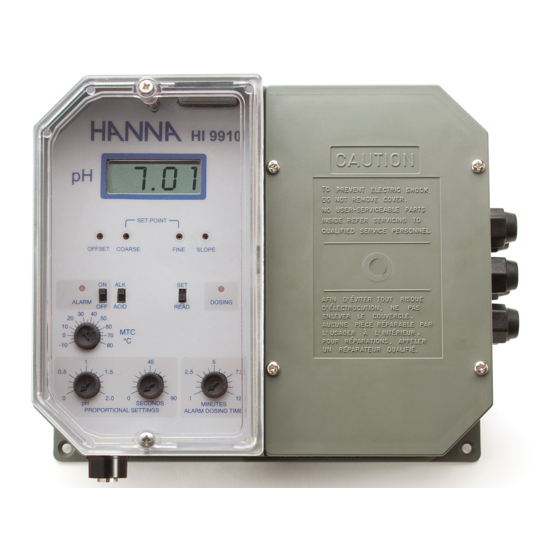
Page 6: Functional Diagram Hi 9910
FUNCTIONAL DIAGRAM HI 9910 FUNCTIONAL DIAGRAM HI 9910 FUNCTIONAL DIAGRAM HI 9910 FUNCTIONAL DIAGRAM HI 9910 FUNCTIONAL DIAGRAM HI 9910 SINGLE SETPOINT, SINGLE SETPOINT, p p p p p H CONTROLLER SINGLE SETPOINT, H CONTROLLER H CONTROLLER H CONTROLLER SINGLE SETPOINT, SINGLE SETPOINT, H CONTROLLER FRONT PANEL... - Page 7 16. Recorder output contacts 17. Automatic or Manual Temperature Compensation switch 18. 0 to 20 or 4 to 20 mA isolated output switch 19. Triple contact alarm in a Normally Closed (NC) or a Normally Open (NO) position. 20. Powered dosage terminals (Relay) 21.
- Page 8 Specifications HI 9910 RANGE 0.00 to 14.00 pH RESOLUTION 0.01 pH ACCURACY ±0.02 pH (@20°C/68°F) TYPICAL EMC ±0.1 pH DEVIATION mA OUTPUT User-selectable 0 to 20 mA or 4 to 20 mA over the 0-14 pH range with isolated output CALIBRATION Through "OFFSET"...
-
Page 9: Functional Diagram Hi 9911
FUNCTIONAL DIAGRAM HI 9911 FUNCTIONAL DIAGRAM HI 9911 FUNCTIONAL DIAGRAM HI 9911 FUNCTIONAL DIAGRAM HI 9911 FUNCTIONAL DIAGRAM HI 9911 DUAL SETPOINT, DUAL SETPOINT, DUAL SETPOINT, pH pH pH pH pH CONTROLLER CONTROLLER CONTROLLER CONTROLLER DUAL SETPOINT, DUAL SETPOINT, CONTROLLER FRONT PANEL HI 9911 ALARM... - Page 10 18. 0 to 20 or 4 to 20 mA isolated output switch 19. Triple contact alarm in a Normally Closed (NC) or a Normally Open (NO) position. 20. Powered dosage terminals (Relays) 21. 110/115V or 220/240V power configuration 22. Incoming power terminals 23.
- Page 11 Specifications HI 9911 RANGE 0.00 to 14.00 pH RESOLUTION 0.01 pH ACCURACY ±0.02 pH (@20°C/68°F) TYPICAL EMC ±0.1 pH DEVIATION mA OUTPUT User-selectable 0 to 20 mA or 4 to 20 mA over the 0-14 pH range with isolated output CALIBRATION Through "OFFSET"...
-
Page 12: Functional Diagram Hi 9920
FUNCTIONAL DIAGRAM HI 9920 FUNCTIONAL DIAGRAM HI 9920 FUNCTIONAL DIAGRAM HI 9920 FUNCTIONAL DIAGRAM HI 9920 FUNCTIONAL DIAGRAM HI 9920 ORP CONTROLLER ORP CONTROLLER ORP CONTROLLER ORP CONTROLLER ORP CONTROLLER FRONT PANEL HI 9920 ALARM mA OUTPUT 4/20 0/20 SET POINT COARSE FINE ALARM... - Page 13 20. Powered dosage terminals (Relay) 21. 110/115V or 220/240V power configuration 22. Incoming power terminals 23. Fuses BOTTOM CONNECTION 24. Female BNC socket for combination ORP electrode 25. 4-mm Banana socket for ground probe Unplug the instrument from the power supply before wiring and replacing the fuses.
-
Page 14: Connections & Wiring
Specifications HI 9920 RANGE -500 to 1500 mV RESOLUTION 1 mV ACCURACY ± 5 m V (@20°C/68°F) TYPICAL EMC ±6 mV DEVIATION mA OUTPUT User-selectable 0 to 20 mA or 4 to 20 mA over the -500 to 1500 mV range with isolated output CALIBRATION Through "CAL"... - Page 15 Before Before • Before Before Before connecting the controller to the mains, wire connecting the controller to the mains, wire connecting the controller to the mains, wire connecting the controller to the mains, wire connecting the controller to the mains, wire the controller completely the controller completely the controller completely...
- Page 16 RELAY CONNECTIONS • Wire the external device or devices (pumps or electrovalves) directly to the relay terminal strip of the controller (see 20 - Functional Diagram). The terminals are powered terminals are powered terminals are powered terminals are powered and hence terminals are powered do not need an external power supply do not need an external power supply...
- Page 17 • The alarm ON/OFF switch is only to disable disable disable disable disable the alarm terminal the alarm terminal the alarm terminal the alarm terminal the alarm terminal (e.g. the buzzer will ALARM not sound). However, all other functions such as disactivation of the dosing relay remain unvaried, i.e.
- Page 18 TEMPERATURE COMPENSATION (HI 9910 and HI 9911 only) • Manual Temperature Compensation: Move the selector to the MTC position (see 17-Functional Diagram). Then manually set the temperature by turning the dial (see 10 - Functional Diagram) to the correct working temperature. °C Temp.
-
Page 19: Normal Operation & Measurement
NORMAL OPERATION and NORMAL OPERATION and NORMAL OPERATION and NORMAL OPERATION and NORMAL OPERATION and MEASUREMENT MEASUREMENT MEASUREMENT MEASUREMENT MEASUREMENT Make sure that the controller has been properly calibrated before commencing and that the pH or ORP setpoint(s) have been adjusted (see the following pages). -
Page 20: Ph Calibration
pH pH pH pH pH CALIBRATION CALIBRATION CALIBRATION CALIBRATION CALIBRATION (HI 9910 and HI 9911) Make sure that the pH electrode and any ground probe have been properly connected and wired to the controller (see preceding pages) and that the meter is plugged to the mains. Calibration should be ideally performed at a temperature similar to that of the liquid to be monitored. - Page 21 as that on the Checktemp and make sure the selector is in the MTC position (see 17 - Functional Diagram). • Wait for the measurement to stabilize and then adjust the "OFFSET" trimmer to display pH 7.01 7.01 on the LCD if the tempera- ture of the buffer solution is at 25°C (77°F).
-
Page 22: Orp Calibration
ORP CALIBRATION ORP CALIBRATION ORP CALIBRATION ORP CALIBRATION ORP CALIBRATION (HI 9920) Make sure that the ORP electrode and any ground probe have been properly connected and wired to the controller (see preceding pages) and that the meter is plugged to the mains. Remove the electrode cap if it is still on the electrode. -
Page 23: Adjustement Of Setpoint(S)
ADJUSTEMENT OF SETPOINT(S) ADJUSTEMENT OF SETPOINT(S) ADJUSTEMENT OF SETPOINT(S) ADJUSTEMENT OF SETPOINT(S) ADJUSTEMENT OF SETPOINT(S) Make sure that the electrode (and any ground probe) is properly installed and calibrated (see the preceding pages). FOR HI 9910 Turn the switch to the "SET" position (see 7 - Functional Diagram). The display will show the previously adjusted value (e.g. - Page 24 e.g. Dosing base liquids ACID Set point = pH 6.00 Measured value = pH 4.00 To adjust the sample stream to the setpoint, you need to dose base, therefore select "ALK". FOR HI 9911 (DUAL-POINT ADJUSTMENT) a) ACID SETPOINT and DOSAGE Turn the switches to "SET"...
- Page 25 Using a small screwdriver, adjust the “ALKALINE SET” trimmers. First adjust the “COARSE” trimmer and then fine tune with the “FINE” 5.18 5.00 ACID SET ACID SET OFFSET COARSE FINE SLOPE OFFSET COARSE FINE SLOPE ALKALINE SET ALKALINE SET trimmer (see 3 and 4 - Functional Diagram) until the desired set value is displayed (e.g.
-
Page 26: Proportional Control
DOSING DIRECTION Select the direction of dosing through the "OXID"/”RED” switch (see 8 - Functional Diagram). For reducing dosage (i.e. lowering the mV value) leave the selector on "RED". Likewise, for oxidizing solutions (to increase the mV) select the “OXID” position. e.g. - Page 27 e.g. pH proportional control Setpoint = pH 5.00 Measured value = 6.50 Delta = 6.5 - 5.0 = 1.5 pH Proportional settings: pH set to 2 and time cycle to 60 seconds. SECONDS PROPORTIONAL SETTINGS The controller will be dosing acids to reduce pH to the desired limit. Since it is 1.50/2.00 = 75% away from the ideal setting, it will keep the dosing terminals D pH...
- Page 28 .g. ORP proportional control Setpoint = 725 mV Measured value = 700 mV Delta = 725 - 700 = 25 mV Proportional settings = mV set to 100 and time cycle to 60 seconds. SECONDS PROPORTIONAL SETTINGS The controller will be dosing reductants to reduce redox to the desired value.
-
Page 29: Overdosage Timer
O V E R D O S A G E T I M E R O V E R D O S A G E T I M E R O V E R D O S A G E T I M E R O V E R D O S A G E T I M E R O V E R D O S A G E T I M E R All models provide for an overdosage alarm... -
Page 30: Ph Values At Various Temperatures
VALUES AT VARIOUS VALUES AT VARIOUS pH VALUES AT VARIOUS VALUES AT VARIOUS VALUES AT VARIOUS TEMPERATURES TEMPERATURES TEMPERATURES TEMPERATURES TEMPERATURES Please refer to the following chart for a more accurate pH calibration: TEMP pH VALUES °C °F 4.01 6.86 7.01 9.18 10.01... -
Page 31: Redox Measurement (Hi 9920)
R E D O X M E A S U R E M E N T R E D O X M E A S U R E M E N T R E D O X M E A S U R E M E N T R E D O X M E A S U R E M E N T R E D O X M E A S U R E M E N T (HI 9920) - Page 32 between 200 and 250 mV. When not in use, the electrode tip should be kept moist in order for the reference junction, especially Teflon models, to respond quickly. Otherwise, soak the electrode overnight in a HI 70300 storage solution or allow more time upon installation for its stabilization. Also keep the electrode far from any type of mechanical stress which might cause damage.
-
Page 33: Electrode Conditioning & Maintenance
ELECTRODE CONDITIONING ELECTRODE CONDITIONING ELECTRODE CONDITIONING ELECTRODE CONDITIONING ELECTRODE CONDITIONING & MAINTENANCE & MAINTENANCE & MAINTENANCE & MAINTENANCE & MAINTENANCE PREPARATION Remove the protective cap. DO NOT BE ALARMED IF ANY SALT DEPOSITS ARE PRESENT. This is normal with electrodes and they will disappear when rinsed with water. -
Page 34: Suggested Installations For Ph/Orp Electrodes
TROUBLESHOOTING Evaluate your electrode performance based on the following. • Noise (Readings fluctuate up and down) could be due to a clogged/dirty junction: Refer to the Cleaning Procedure above. • Dry Membrane/Junction: Soak in Storage Solution HI 70300 overnight. Check to make sure the installation is such as to create a well for the electrode bulb to constantly remain moist. -
Page 35: Accessories
MEDIUM DISTANCE, INDOOR/OUTDOOR INSTALLATION When an outdoor installation is required, it is normally necessary to install a transmitter to obtain accurate readings at distances from 10 to 50 m (33-165'). Since the introduction of AmpHel electrodes these distances are no longer a problem. - Page 36 pH CALIBRATION SOLUTIONS HI 7004L pH 4.01 buffer solution, 460 mL HI 7007L pH 7.01 buffer solution, 460 mL HI 7010L pH 10.01 buffer solution, 460 mL ORP SOLUTIONS HI 7020L 200-275mV ORP solution, 460 mL HI 7091L Pretreatment reducing solution, 460 mL HI 7092L Pretreatment oxidizing solution, 460 mL ELECTRODE STORAGE SOLUTION...
-
Page 37: Warranty
If the repair is not covered by the warranty, you will be notified of the charges incurred. If the instrument is to be returned to Hanna Instruments, first obtain a Returned Goods Authorization Number from the Cus- tomer Service department and then send it with shipment costs prepaid. -
Page 38: Other Products From Hanna
OTHER PRODUCTS FROM HANNA OTHER PRODUCTS FROM HANNA OTHER PRODUCTS FROM HANNA OTHER PRODUCTS FROM HANNA OTHER PRODUCTS FROM HANNA • CABLES AND CONNECTORS • CALIBRATION AND MAINTENANCE SOLUTIONS • CHEMICAL TEST KITS • CHLORINE METERS • CONDUCTIVITY/TDS METERS • DISSOLVED OXYGEN METERS •... -
Page 39: Ce Declaration Of Conformity
CE DECLARATION OF CONFORMITY CE DECLARATION OF CONFORMITY CE DECLARATION OF CONFORMITY CE DECLARATION OF CONFORMITY DECLARATION OF CONFORMITY Hanna Instruments Srl V.le delle industrie 12 35010 Ronchi di Villafranca (PD) ITALY herewith certify that the wall-mounted instruments: HI 9910 HI 9911 HI 9920... - Page 40 HANNA LITERATURE HANNA LITERATURE HANNA LITERATURE HANNA LITERATURE HANNA LITERATURE Hanna publishes a wide range of catalogs and hand- books for an equally wide range of applications. The reference literature currently covers areas such as: • Water Treatment • Process •...
Need help?
Do you have a question about the HI 9910 and is the answer not in the manual?
Questions and answers