
Related Manuals for Hanna Instruments HI 504


Summary of Contents for Hanna Instruments HI 504
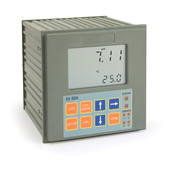
- Page 1 HI 504 Panel-mounted, Microprocessor-based pH/ORP Process Controller Instruction Manual...
-
Page 2: Table Of Contents
TABLE OF CONTENTS WARRANTY ......4 MODEL IDENTIFICATION ....5 PRELIMINARY EXAMINATION . -
Page 3: Warranty
If the instrument is to scheme: be returned to Hanna Instruments, first obtain a Returned Goods Authorization number from the Customer Service de- partment and then send it with shipping costs prepaid. When shipping any instrument, make sure it is properly packaged for complete protection. -
Page 4: Preliminary Examination
• Calibration and Setup procedures are password protected. PRELIMINARY EXAMINATION • Calibration: pH calibration at 2 points with two possible sets Remove the instrument from the packing material and exam- of buffers (either 7.01 - 4.01 - 10.01 or 6.86 - 4.01 - 9.18), or at 1 point with user-selectable value. -
Page 5: Functional Description
REAR PANEL FUNCTIONAL DESCRIPTION FRONT PANEL 1. Liquid Crystal Display 1. BNC Socket for pH or ORP electrode 2. Connection for Potential Matching Pin 2. LCD key enters and exits the event scrolling mode. During pH 3. Connection for electrode reference calibration, alternately displays pH buffer value or current temperature 4. -
Page 6: Specifications
SPECIFICATIONS Range -2.00 to 16.00 pH Alarm Relay Electromechanical Relay SPDT contact output, -2000 to 2000 mV 5A - 250 VAC, 5A - 30 VDC (resistive load) -30 to 130.0 ºC Fuse protected: 5A, 250V Quick Blow Fuse Resolution 0.01 pH Analog Output •... -
Page 7: Installation
• Electrode: Connect the pH or ORP electrode to the BNC INSTALLATION socket (#1 at page 9). To benefit from the differential (symmetrical) input, connect Refer to diagram on page #9 the proper electrode wire (if available) or a cable with a potential matching pin (grounding bar) to the relevant ter- minal (#2 at page 9) and enable the differential input through the setup code I.04. -
Page 8: Calibration Mode
The pH and ORP calibrations can not be initiated while the CALIBRATION MODE process controller is configurated to take measurements from the Digital Transmitter. The calibration mode allows to calibrate the pH/ORP input, temperature input and 4-20 mA analog outputs. pH CALIBRATION The controller is factory calibrated for all these parameters. - Page 9 The default buffer set is the one used for last calibration, • In the second case (pH value not close to the buffer) the even if the procedure was not completed. meter will remain in the same state until the reading be- comes unstable or the calibration mode is quitted.
- Page 10 • The pH calibration value will switch • When the reading becomes stable, if the ORP value is to 7.00, the first digit starts blinking close to the calibration point, the “CFM” indicator starts and it is possible to change its value blinking;...
- Page 11 • Once visualized the selected output, press the key to Note The instrument can support Pt100 or Pt1000 temperature choose the range of the analog output (0-20 mA or 4-20 sensor and calibration can be performed with anyone of these mA);...
- Page 12 is exited (by pressing the CAL key). The meter will proceed showing the scrolling message “Press CFM to confirm the current buffer or right to escape” (to • When performing the second calibration point, it is pos- prevent from confirming the calibration point inadvertently). sible to choose between two values, 25°C and 50°C.
-
Page 13: Setup Mode
SETUP MODE • When the whole password has been in- serted, press CFM to confirm it. The Setup Mode allows the user to set all needed character- Note The default password is set at “0000”. istics of the meter. To enter the mode, press the SETUP key and enter the password when the device is in idle or ENTERING SETUP ITEMS control mode. - Page 14 Note While in the setup mode, if no activity is performed for about 5 minutes after entering the setup mode, the mode is auto- matically exited and the instrument returns to the previous mode. The below table lists the setup codes along with the description of Otherwise, if a numeric value has to be entered for the the specific setup items, their valid values and whether the item is item, use the æ...
- Page 15 Code Valid Values Default Present Code Valid Values Default Present for ORP for ORP C.12 Hysteresis for setpoint 1 (H1) 0.00 to 18.00 pH or 1 pH or C.51 Monday hold mode “OFF”: Disabled “OFF” (see note 1) 0 to 4000 mV 50 mV enable “On”: Enabled...
- Page 16 Code Valid Values Default Present Code Valid Values Default Present for ORP for ORP 0.05 Hold digital output “OFF”: Disabled “HOLd” O.24 Analog output 2 value upon “USEr”: User selected value “HOLd” “HOLd”: Enabled upon hold mode hold mode (see note 16) “HOLd”: Previous value is frozen O.25 Analog output 2 value upon -30 to 130.0 ºC 25ºC...
- Page 17 Code Valid Values Default Present Code Valid Values Default Present for ORP for ORP r.02 Current year 2000 to 2099 (see note 20) from RTC (5) SOLUTION COMPENSATION (“SOLC”) r.03 Current time 00:00 to 23:59 (see note 20) from RTC (5) S.00 Solution compensation enable “On”: compensation enabled “OFF”...
- Page 18 Code Valid Values Default Present Code Valid Values Default Present for ORP for ORP ERROR CONFIGURATION (“Erro”) TEST (“tESt”) E.00 Alarm for setpoint 1 0 to 5 t.00 Display test “OFF”: To skip without testing “OFF” error configuration and 24 to 29 (see note 7) “GO”: To start the display test E.01 Alarm for setpoint 2 0 to 5...
- Page 19 if M2 = “PIdL” then D2 A2 and -2.00 pH or -2000 mV S2-A2; if M1 = “OOHI” and M2 = “OOLO” then S1-H1 S2+H2; if M1 = “OOLO” and M2 = “OOHI” then S2-H2 S1+H1; if M1 = “PIdH” and M2 = “OOLO” then S1 S2+H2;...
- Page 20 (8): The hold mode is never enabled by the control timing if lecting “LE” for “level”) or with a pulse (by selecting “PULS” the “hold time start” is the same as the “hold time end”. for “pulse”). The pulse length is fixed to about 5 seconds. Items “C.41”...
- Page 21 or PID) or low (ON/OFF or PID) setpoint respectively. The (29): Every SMS sent by the instrument requires a reception same is true for Alarm relay delta value for setpoint 2. A confirmation from the user (phone call to the instrument). If small fixed hysteresis (0.2 pH for pH and 30 mV for ORP) this confirmation does not arrive (for example because the must be passed to have the alarm turned off (for a high...
-
Page 22: Control Mode
In the first two cases the configuration of Setpoint (1 or 2) CONTROL MODE determines the operating mode of the relay. Once enabled, the control relay can be configured to control as a ON/OFF The control mode is the normal operational mode for this meter. or PID control of the acid/base dosage. - Page 23 sure falls below setpoint value minus hysteresis. The following graph describes the pH process controller be- havior. Similar graph may apply to the mV controller. Such a behavior is suitable to control an acid dosing pump. During proportional control the process controller calculates the relay activation time at certain moments t etc.
- Page 24 PID TRANSFER FUNCTION TUNING A PID CONTROLLER The transfer function of a PID control is as follows: The proportional, integrative, derivative terms must be tuned, i.e. adjusted to a particular process. Since usually the pro- Kp + Ki/s + s Kd = Kp(1 + 1/(s Ti) +s Td) cess variables are not completely known, a “trial and error”...
- Page 25 pH or mV value. Read the system time delay Tx on the time axis. An hysteresis will eliminate the possibility of continuous se- quences ‘energizing/de-energizing’ of the alarm relay when 4. The deviation, Ti and Td can be calculated from the following: •...
-
Page 26: In-Line Cleaning
and the external alarm circuit. IN-LINE CLEANING The cleaning feature allows an automatic cleaning action of the electrodes. To perform cleaning, the controller activates an external device (pump). Cleaning can be of two types: • Simple cleaning: with water only, it can be triggered only by a timer (periodical cleaning) or by an error for which a cleaning action can be configured (i.e. - Page 27 Note • Hold mode end delay (set by item C.70): if the device If a cleaning session is being performed, it is possible to stop was controlling when the cleaning action started, then the it by pressing and holding the keys together ( hold mode end delay must expire before restarting control.
-
Page 28: Idle Mode
IDLE MODE HOLD MODE During idle mode the device performs only measurements This function is started by: but it does not activate relays in order to control the process • calibration; or let out a control signal to the analog output. •... -
Page 29: Analog Output
ANALOG OUTPUT All the alarm signals (red LED, alarm relay, fault currents) are suspended while in hold mode (the correspondent error events are not closed), unless the hold mode is being triggered by The meter is provided with two insu- one or more errors and no other trigger source (different from lated current outputs. -
Page 30: Pc Communication
® with the HI 92500 Windows compatible application soft- ware offered by Hanna Instruments and an RS232 to RS485 adapter with Send Data Control connected to the serial port of your PC. There is an internal short between the two A pins and be- The user-friendly HI 92500 offers a variety of features such tween the two B pins. - Page 31 Line conditions, pull-up and pull-down resis- Following is the complete list of commands available: tors should be connected as shown. The Fail-Safe resistors are connected only to Command Parameter Remarks one unit in the line, and their value depends on the application and characteristic imped- NNMDR not available Requests firmware code...
- Page 32 Following are examples for setup item format: Command Parameter Remarks • item C.32, maximum relay ON time parameter value = NN EVN not available Requests new events 15, format = “+015 “, where indicates a blank; (always available) • item C.21, setpoint 2 value while in ORP mode: parameter NN AER not available Requests active errors...
- Page 33 4) “NN”, CAN (char 0x18) if the process controller can not where S means “status” and can be equal to “A” (control and answer to the request (e.g. the current process model does alarm ON), “C” (control ON and alarm OFF), “N” (control not support the request, the given general password is OFF).
- Page 34 ON; bit 2 = 1 and bit 1 = 1: LED blinks) a 1-point calibration is performed) it is indicated with a “N” letter. bit 3 relay #1 (1: energized, 0: de-energized) 2) Process controller configured for ORP: bit 4 relay #2 (1: energized, 0: de-energized) If mV is not calibrated: “NN<STX>0<ETX>”...
- Page 35 • for calibration events: date and time of a calibration; Here is the format for answer to NNEVN<CR>: • for cleaning events: start date and time of cleaning action. “NN<STX>0<ETX>” if there is no new event, otherwise: The meaning of “end_date ”...
-
Page 36: Short Messaging Service (Sms)
The meaning of B SHORT MESSAGING SERVICE (SMS) bit 0 Alarm for setpoint 1 It is possible to connect the Hanna HI 504900 GSM mod- bit 1 Alarm for setpoint 2 ule to the RS485 port of the instrument. This connection enables bit 2 Maximum relay ON time exceeded the instrument to send SMSs to one (or two) cellular phone(s) - Page 37 When the desired phone number is entered, press CFM to confirm. The WRONG tag will blink if the user tries to confirm an incorrect number (the first digit of the number has to be on the first position and the “-” character have not to be present By pressing the key, the first digit will be fixed on and it will in the middle of the number).
- Page 38 the cellular module initialized and to the activated error. the SMS service activated. During Here is reported a list of all the possible error strings: the reading of the SIM card, “CELL” • “Alarm for setpoint 1” and the MEM tag will blink alter- •...
- Page 39 and no confirmation waited), while the P .06 item sets the The information about SIM charge and expiration date are delay (in minutes) between two subsequent messages. not saved in the SIM card but are managed by the network operator; the instrument can not get directly the information. To prevent the discharge of the SIM card, the user has to When the instrument receives a phone call (coming from configure manually (accordingly with the credit stored on the...
-
Page 40: Modem Connection
reset when the expiration date is changed. If the expiration MODEM CONNECTION date is reached without any updating of the items P .07 - P .09, then the “Cellular error” will be switched on and no more A modem connection can be established between HI504 messages will be sent by the instrument until the error is and a remote computer over telephone line. - Page 41 The modem connection (both with HI504900 and HI504902) When making a call, after the data connection is established, allows the user to ask the controller from a remote position the “NNPWD...” command (where “NN” is the address of about its status, measurements and to change some param- the device controlling the modem, i.e.
-
Page 42: Ph/Orp Probe Check
pH/ORP PROBE CHECK SOLUTION COMPENSATION The pH electrode and the reference electrode for both pH The instrument is provided with a solution compensation func- and ORP can be automatically monitored through HI 504. tion which can be enabled through setup menu (setup item Setup items involved are I.13 (pH electrode impedance test S.00). -
Page 43: Temperature Compensation
For quickly changing the temperature value press and hold TEMPERATURE COMPENSATION down the æ (or ) key: the temperature will be incremented (decremented) of 0.1°C until the total amount is 0.4°C, and If the setup item G.01 is set to “AtC” an automatic tempera- then the increment (decrement) will turn to 1°C. -
Page 44: Last Calibration Data
Pressing the key, the meter will cycle through the following LAST CALIBRATION DATA steps in reverse order, i.e. beginning from last buffer. If the meter is set as pH controller, the following data about Note At any time pressing LCD or CAL DATA key the meter will the last calibration are stored in the EEPROM: return to the regular operating display. -
Page 45: Offset And Slope Direct Selection
• If an offset calibration has been OFFSET AND SLOPE DIRECT SELECTION made, the instrument will turn to “slope” calibration (as indicated by It is possible to edit directly the values of the offset and the the “SLO” message on the second- slope to calibrate the instrument. -
Page 46: Event Log File Scrolling
• for cleaning events: EVENT LOG FILE SCROLLING • start date • start time The event log file is composed by a maximum of 100 re- • type of cleaning (“AdCL” for advanced corded events, which include errors, calibration events (type cleaning;... -
Page 47: Fault Conditions
If the error is due to impossible communication with the FAULT CONDITIONS EEPROM or the RTC, all the pH/ORP controller tasks are stopped, the alarm relay is de-energized, the red LED blinks The below fault conditions may be detected by the software: and the “Serial bus error”... - Page 48 • The display test is announced by a scrolling “Display test” message. For example, if SETUP and æ keys are pressed together the • All the segments light up for a LCD will look like this: few seconds and then switch off before exiting the display test pro- cedure and moving to the next setup item (t.01).
- Page 49 • During this time the instrument performs the EEPROM check, and if the checksum is correct, the “Stored data good” message will scroll on the primary display. • Some keys are used to toggle relays and LEDs ON and OFF: - the LCD key toggles the alarm relay and the alarm LED;...
- Page 50 value of the analog output type chosen with setup item a blinking “GO”. O.11 (analog output 1) and O.21 (analog output 2). • Press CFM key to confirm or the æ ) key again to • A new output value can be edited manually. It is possible return to the previous status.
-
Page 51: Alarm - Error Configuration
ing (setup item L.14). ALARM - ERROR CONFIGURATION • To exit the test press the CFM key; the instrument will re- This section is dedicated to all the possible error causes for main in the setup menu and move to the next setup item (t.08). - Page 52 (*): When the Digital Transmitter is used, these errors are with the cellular engine (for example because the serial generated in the Digital Transmitter, but they are handled as cable is broken or because the cellular engine is not pow- if they were generated in the Process Controller.
-
Page 53: Ph Values At Various Temperatures
pH VALUES AT VARIOUS TEMPERATURES ELECTRODE CONDITIONING AND MAINTENANCE Temperature has a significant effect on pH. The calibration PREPARATION buffer solutions are effected by temperature changes to a lesser Remove the electrode protective cap. degree than normal solutions. DO NOT BE ALARMED IF ANY SALT DEPOSITS ARE For manual temperature calibration please refer to the fol- PRESENT. - Page 54 PERIODIC MAINTENANCE - Make sure cable and connections are not damaged nor lying in a pool of water or solution. Inspect the electrode and the cable. The cable used for the connection to the controller must be intact and there must be •...
-
Page 55: Definitions
ACCESSORIES DEFINITIONS pH CALIBRATION SOLUTIONS DEVIATION Same as proportional band, but expressed in units of the controlled magnitude (e.g. 1pH, 50 mV). HI 7004M or HI 7004L pH 4.01 Buffer Solution, 230 or 500 ml bottle HI 7006M or HI 7006L pH 6.86 Buffer Solution, 230 or 500 ml bottle EEPROM Electrically Erasable Programmable Read-only Memory (per-... - Page 56 pH AND ORP ELECTRODE HOLDERS HI 60542 In-line electrode holder for direct pipe installation HI 7611 Stainless steel Pt1000 probe with standard 1/2’’ external threads on both ends for in-line and immersion installation; 5 m (16.5’) cable HI 7621 Glass Pt1000 probe with external PG13.5 thread and 5 m (16.5’) cable HI 60542-0 1 set of O-rings for HI 60542 electrode holder...
- Page 57 AND ORP ELECTRODES channels Hanna Instruments produces a wide range of pH and ORP electrodes specifically de- signed for needs of industrial uses. For a complete list of available electrodes visit our web site at www.hannainst.com or contact your dealer.
-
Page 58: Ce Declaration Of Conformity
UNDERWRITERS LABORATORIES APPROVAL CE DECLARATION OF CONFORMITY The HI 504 process controllers series complies with the pro- duction standards required by the Underwriters Laboratories (UL), one of the most important international authority for devices' safety, and has therefore obtained the UL certifica- tion. - Page 59 SALES AND TECHNICAL SERVICE CONTACTS Australia: Tel. (03) 9769.0666 • Fax (03) 9769.0699 China: Tel. (10) 88570068 • Fax (10) 88570060 Egypt: Tel. & Fax (02) 2758.683 Germany: Tel. (07851) 9129-0 • Fax (07851) 9129-99 Greece: Tel. (210) 823.5192 • Fax (210) 884.0210 Indonesia: Tel.
Need help?
Do you have a question about the HI 504 and is the answer not in the manual?
Questions and answers