
Related Manuals for Hanna Instruments HI 9914


Summary of Contents for Hanna Instruments HI 9914
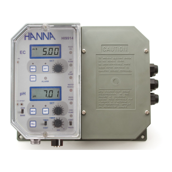
- Page 1 Instruction Manual HI 9914 Wall mounted Fertigation Controller w w w . h a n n a i n s t . c o m...
-
Page 2: Table Of Contents
GENERAL DESCRIPTION SPECIFICATIONS................8 INSTALLATION ................10 TANK ASSEMBLY SETUP .............. 10 HI 9914 wall mounted fertigation controller is designed to meet specific CONNECTIONS AND WIRING ............12 process control requirements in agricultural, horticultural and hydropon- CONTROLLER START-UP .............. 18 ics applications. -
Page 3: Mechanical Layout
Two models are available, with different power supply input: The molded mounting holes in the 4 corners provide for quick and secure • HI 9914-1 works with 110/115 Vac input installation. No additional tool is needed. All the electrical connections •... -
Page 4: Functional Description
FUNCTIONAL DESCRIPTION RIGHT PANEL LEFT PANEL 1. Connections for matching pin 2. EC analog output 3. pH analog output 4. Level sensors input 1. LCD for Conductivity readings 5. Mains power fuse 2. EC SET button 6. Fuse for pH and EC correction dosing pumps 3. -
Page 5: Specifications
Bottom view Analog output 0-7V ±5% (0.5V / pH) Controller Output 2A, 220V relay Other Features Timer Adjustable, from 1 to 10 minutes within a 15-minutes-time frame Feed OK output 12V, 15 mA current source Humidity sensor Activated if resistivity is below 220 KΩ Water nozzle output 2A, 220V relay Circulation pump output... -
Page 6: Installation
Typical arrangements for the Tank assembly INSTALLATION Install the HI 9914 controller on a wall, indoors, in a dry area and not under direct sun light. Assure that liquids can not be sprayed or poured on it. Fix the controller at a proper height to easily reach the front panels and fix the 4 screws at the 4 corners. -
Page 7: Connections And Wiring
• If the matching pin is used, connect the matching pin terminal to the con- nector pin 2 located on the right panel. • Immerse the matching pin near the pH electrode. Minimal tank assembly: only the normal level sensor is used, the irriga- tion is made manually, regardless of the water composition or level. - Page 8 • Place the low-level sensor to indicate the minimum water level for the External fill button connection correct function of both the circulation and feeding pumps. • Connect the button • Connect the sensor between INPUT COMMON and LOW LEVEL pins. between FILL and IN- •...
- Page 9 pin is the same, so that the voltage of the power source has to match the Water nozzle, Circulation and Feeding pump connection working voltage of the selected device and both the pH and EC correction The Water nozzle, Circulation pump and Feeding pump outputs are pumps have to work at the same voltage.
-
Page 10: Controller Start-Up
NORMAL OPERATION Before starting-up make sure the controller has been properly calibrated, When the HI 9914 controller is turned on, the meter performs a status and the pH and conductivity setpoints have been adjusted (see the check of the level sensors and provides the commands depending on the following pages). - Page 11 If the CONT/PAUSE switch of the Circulation pump is in Step 4: CONT position, the circulation pump will act as described The water nozzle is closed, circulation pump is running and the Conduc- tivity & pH controls are activated. The Conductivity control has the above.
-
Page 12: Alarm Conditions
CONTROLLER SETTINGS ALARM CONDITIONS SETTING THE pH CONTROL When an alarm condition is reached, the ALARM LED turns ON and the To adjust the pH setpoint: alarm relay contact is closed (short between the COMMON and NO pins). • Press the SET button close to the pH display to read the setpoint value. All the pumps and the water nozzle are off. - Page 13 • Turn the SET knob until the display shows the desired value. SETTING THE CIRCULATION PUMP WORKING REGIME •Turn back in measurement mode by pressing the MEA button. • Set the CONT/PAUSE switch to CONT to enable a continuous running Note: The internal pH and EC regulators have a small hysteresis to of the Circulation pump (if no ALARM condition is present).
-
Page 14: Calibration
Slope adjustment CALIBRATION • Rinse the electrode and the ground probe thoroughly with water and immerse the Disconnect the pumps, the water nozzle and the alarm or assure that the bottom 4 cm (1.5") in a pH10.01 (HI 7010) start of one of them will cause no damage. or a pH4.01 (HI 7004) buffer solution. -
Page 15: Ph Electrode Conditioning & Maintenance
• Stir the probe and tap it gently to the pH ELECTRODE CONDITIONING bottom of the beaker to ensure that any air bubbles trapped inside it. & MAINTENANCE For best results, do not put the probe close to the walls of the beaker or lying Preparation on the bottom. -
Page 16: Conductivity Probe Maintenance
Troubleshooting CONDUCTIVITY PROBE MAINTENANCE Evaluate the electrode performance based on the following: • Noise (readings fluctuate up and down) could be due to clogged/dirty junction: Preparation Make sure that the protective sleeve is on the probe shaft and is intact. - Dry Membrane/Junction: soak in HI 70300 Storage Solution overnight. -
Page 17: Accessories
- Air bubbles also disturb measurements and the probe should be APPENDIX - A installed in such a way as to minimize them. Note: It is always recommended to keep at least one spare probe handy. When anomalies are not resolved with a simple mainte- pH VALUES AT VARIOUS TEMPERATURES. -
Page 18: Appendix
APPENDIX - B Composition of nutrient solution for several plants growth in hydroponic system utilized in nursery and cutting plants cultivation. Reference: “Principi tecnico-agronomici della fertirrigazione e del fuori suolo”, pag.115, published by “Veneto Agricoltura-Centro Sperimentale Ortofloricolo Po di Tramontana”, coordinator Prof. F.Pimpini, Agricultural Faculty, Univer- sity of Padova - Oct. -
Page 19: C-Installation Examples
APPENDIX - C INSTALLATION EXAMPLES Block diagram for a typical installation of an irrigation system, with Block diagram for an irrigation system with recirculation circuit. HI9914 controller. -
Page 20: Warranty
If the repair is not covered by the warranty, you will be notified of the charges incurred. If the instrument is to be returned to Hanna Instruments, first obtain a Returned Goods Authorization Number from the Customer Service de- partment and then send it with shipment costs prepaid. - Page 21 SALES AND TECHNICAL SERVICE CONTACTS Australia: Tel. (03) 9769.0666 • Fax (03) 9769.0699 China: Tel. (10) 88570068 • Fax (10) 88570060 Egypt: Tel. & Fax (02) 2758.683 Germany: Tel. (07851) 9129-0 • Fax (07851) 9129-99 Greece: Tel. (210) 823.5192 • Fax (210) 884.0210 Indonesia: Tel.
Need help?
Do you have a question about the HI 9914 and is the answer not in the manual?
Questions and answers