
Related Manuals for Hanna Instruments HI 8001


Summary of Contents for Hanna Instruments HI 8001
- Page 1 Instruction Manual HI 8001 & HI 8002 Panel-mounted and Wall-mounted Fertigation Controllers These Instruments are in Compliance with the CE Directives Manufacturers since 1978...
-
Page 2: Table Of Contents
Dear Customer, Thank you for choosing a Hanna Product. Please read this instruction manual carefully before using the instrument. This manual will provide you with the necessary information for a correct use of the instrument, as well as a precise idea of its versatility. If you need more technical information, do not hesitate to e-mail us at tech@hannainst.com. - Page 3 5.4 Alarms Consulting ..............37 5.5 Log Consulting ..............37 5.6 General Settings ..............39 5.7 Program Settings ..............40 5.8 Manual Commands .............. 49 5.9 Customized Settings ..............50 6 CALIBRATION PROCEDURES ............57 6.1 Sensor Calibration Procedure ..........57 6.2 PID Calibration Procedure ............
-
Page 4: Theory Of Function
1 THEORY OF FUNCTION Irrigation is one of the most important operation in agriculture. With proper irrigation the quality and quantity of crops can be significantly enhanced. Correct irrigation is not a simple process: the quantity of water must be suffi- cient for crops, and if not, photosynthesis and overall growth is impeded. -
Page 5: General Description
2 GENERAL DESCRIPTION The Fertigation Controller is a micro-processor-based system used in fertiliza- tion and irrigation control for greenhouses or open fields with powerful, flex- ible programming features. The main function of the Fertigation Controller is supplying and controlling the necessary water and fertilizers for crops according to several parameters such as acidity, conductivity and received solar radiation. -
Page 6: Functional Description
3 FUNCTION DESCRIPTION In this chapter the main functions of the Fertigation Controller are presented. For a better understanding see the typical installation schemes utilized for irrigation and fertilization presented in the Installation Block Diagram, Appendix 5. 3.1 IRRIGATION CONTROL The Fertigation Controller can control 8 to 32 sectors (one valve per sector) for each of the ten irrigation programs: - 1 to 32 valves (sectors) can be selected specifying the sector’s number and... - Page 7 - The accumulated solar radiation starting level value is used as a threshold value for the accumulated solar radiation. When the accumulated solar radiation value exceeds this threshold level the irrigation program is started (or it is brought in READY state if there are other programs currently run- ning at that moment).
- Page 8 SOLAR RADIATION FACTOR: - This option can be set using panel S 42 (CORRECTIONS). This factor affects the irrigation time or volume extension in accordance with the set value of the solar radiation sensor level and solar radiation accumulation. The solar radiation accumulation extension setting and current value is displayed on panel C 06 (SOLAR RAD IRRIG).
-
Page 9: Conductivity Control
sectors using one of the following ways: - Manually - Every day at specified hour - Automatically when the accumulations counter value overflows 3.2 CONDUCTIVITY CONTROL Conductivity control is used to control the fertilization and a reading can be obtained with one to three conductivity sensors, one to two for fertilization control and one for water supply conductivity control. -
Page 10: Fertilization Control
3.3 FERTILIZATION CONTROL Fertigation Controller can use up to 4 fertilizer tanks. Each irrigation program can specify the percentage for each type of fertilizer. These values can be set using panel S 39 (SET FERTILIZERS). The fertilization is done in accordance with the conductivity control. Each irriga- tion program has a specified conductivity target value (conductivity reference value which is set using panel S 41 (COND CONTROL);... -
Page 11: Pid Control
AGES). For each individual sector’s pH average see panel C 24 (SECTOR AVERAGES). All pH averages can be deleted manually or at specified time of day using panel S 61 (ERASE STATISTICS). 3.5 PID CONTROL A simplified schematic of the control (pH and EC): EC and pH control is performed using an automatic regulated system with PID controller (Proportional, Integral and Derivative). - Page 13 opening and closing of a valve through which a neutral solution is circulated. The amount of neutral solution added is relative to the opening of the valve, which is directly proportional to the magnitude of difference between the mixing tank pH and the set point. Control of pH implies a complex adjustment.
-
Page 14: Agitator Control
can compensate for changes in the process variable (measurement) and is par- ticularly good for slowly moving processes. When a change occurs in the pro- cess the derivative action causes the controller gain to move the “wrong” way until the measurement gets near the set point. 3.6 AGITATOR CONTROL Each of the 4 fertilizer tanks may have an agitator. -
Page 15: Alarms
- To erase all statistics, use panel S 61 (ERASE STATISTICS). Statistics indi- cates pH and conductivity averages for all irrigation programs and sectors in addition to average total irrigation accumulation. - To erase the settings of one irrigation program or to erase all settings for all irrigation programs, use panel S 62 (ERASE SETTINGS). -
Page 16: Logging (Diary) Functions
3.10 LOGGING FUNCTIONS The Fertigation Controller has the capability to log the most important occurred events and values of different parameters that can offer a description of the evolution of the entire process; The most important values are: - Number and time period of every program activation; - Filter cleaning;... -
Page 17: User Interface
4 USER INTERFACE The Fertigation Controller’s user interface consists of a 4 x 20 character LCD and a 23-key keyboard. Keyboard structure. 4.1 OPERATING MODES The Fertigation Controller operates primarily in two major modes: Consulting Mode Setting Mode User interface panels (screens) are broken down into two categories: 1. - Page 18 different controller entities (programs, sectors, fertilizers etc.) within the same panel. - LEFT and RIGHT ARROWS KEYS can be used to move the cursor within the selected parameter’s limits. - ESC key can be used as a shortcut key to access the C 03 (PROGRAM STATE) panel from any currently viewed panel.
- Page 19 - LEFT, RIGHT arrow keys allow navigation within the currently focused data object. If the cursor exceeds the boundaries of the data object then the focus is transferred to the previous or next editable item within the current panel. - TAB key can be used to move only in a forward direction, from one data object to the next within the selected panel.
-
Page 20: Panels Browsing Methods
4.2 PANEL BROWSING METHODS In consulting mode, two browsing methods are available to view each of the 62 panels (screens) of the Fertigation Controller. - Step-by-step browsing: pressing the PAGE UP and PAGE DOWN keys allow consecutive navigation from one panel to the next. The direction is dependent upon which key is selected. - Page 21 11 SOL RAD EXTENS 40 PH CONTROL MAN CORRECTION 41 COND CONTROL TOTAL CORRECTION 42 CORRECTIONS SECTOR STATE 43 SOLAR RAD IRRIG 15 - 44 - FERTILIZ STATE 45 SET AGITATORS AGITATOR STATE 46 FILTERS CTRL PROG LAST START 47 PROG MAN START TOTAL ACCUMUL 48 PROG MAN STOP PROGRAM ACCUMUL...
-
Page 22: Panel Description
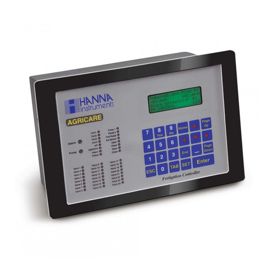
Table This panel is shown during the Fertigation Controller Initialization state; it con- tains the HANNA INSTRUMENTS logo, the name of the controller and the software version. The last line is used to display the current status of the initializa- tion sequence. - Page 23 Although access to the controllers features are denied, the functionality of the controller is not directly effected if a password authentication sequence fails. 5.1.4 GENERAL INFO – C 01 WORK Anomalies Prog 06.4pH Sect 02.1mS 13:15 GENERAL INFO This panel displays the following information starting from top left: Fertigation Controller Functional State (top left corner) When the controller is running it can be in one of the following states: INITIALIZATION, STOP , WORK, BLOCK.
-
Page 24: Consulting Program Settings
NOTE: - If the user is logged in and the operational mode is CONSULTING MODE, this panel can be accessed anytime and from any panel using the HOME key as a shortcut. - The Real Time Clock, pH and EC sensors are always visible regardless of state. - Page 25 5.2.1 PROGRAM STATE – C 03 PROG ACTIVE Started Solar Repeat 02/05 13:15 PROGRAM STATE The purpose of this panel is to allow the user to inspect the status and settings of a particular program. The program number indexes this panel. This panel con- tains the following information: Program Number Reflects the selected program (can be selected only inside panel C 03).
- Page 26 REMINDER: In CONSULTING MODE the ESC key can be used as a short- cut key to access this panel from any panel. 5.2.2 PH STATE – C 04 Prog Ref=06.4pH S1=05.4PH S2=05.5PH 13:15 STATE The purpose of this panel is to allow the user to inspect the current pH reference point for a specific program and the real time pH sensor readings.
- Page 27 and is not program specific. S in = Real time value of EC input sensor. This is an option sensor input to measure the conductivity of the incoming water supply. This reading applies to the entire process and is not program specific. System clock 5.2.4 SOLAR RAD IRRIG –...
- Page 28 Indicates if the selected program is set to run on a daily schedule. Period Indicates if the selected program is set to run on a yearly schedule. System clock 5.2.6 PRIOR & CONFLICTS – C 09 Prog Priority Conflict Programs 13:15 PRIOR &...
- Page 29 This panel displays the current irrigation state of the indexed program. Time or volume can control irrigation and the above panel displays the set value and the amount of irrigation currently completed. The mode of irrigation (time or vol- ume) can be selected using panel S 53 (IRRIG CTRL MODE). The program number indexes this panel.
- Page 30 5.2.9 MAN CORRECTION – C 12 Prog +015% +00:05:55 13:15 CORRECTION This panel displays how much the programmed irrigation parameters are manu- ally modified (corrected). The program number indexes this panel. This panel contains the following information: Program Number Reflects the selected program (can be selected only inside panel C 03). See Section 5.2.
- Page 31 5.2.11 SECTOR STATE – C 14 Prog Sect 21/21 00:10:30+009:45 Done 00:03:10 13:15 SECTOR STATE This panel displays the state of each sector. Each sector has an electro-valve. When a particular sector requires irrigation the electro-valve is opened for a specified period of time.
- Page 32 This panel displays the set and current amount of fertilizer used for a specific program. The Fertigation Controller controls the dosing of 4 fertilizers. In this panel the fertilizer number is used as the index, allowing inspection of the per- cent values for up to four fertilizer tanks involved in the selected irrigation pro- gram.
- Page 33 Pause The set pause time value for the indexed agitator of the selected program. System clock NOTE: The agitator’s working time values can be specified using panel S 45 (SET AGITATORS). 5.2.14 PROG LAST START – C 18 Prog Filter Last start Manual...
-
Page 34: Statistics Consulting
5.3 STATISTICS CONSULTING 5.3.1 TOTAL ACCUMUL – C 19 From: 09-26 13:37;12 0007654L 13:15 TOTAL ACCUMUL This panel provides a total (in time or volume) of the entire irrigation process (all programs) from the reset time. All Fertigation Controller’s statistics including accumulations can be erased (manually, daily at specified hour, on overflow ) within panel S 61 (ERASE STATISTICS). - Page 35 5.3.3 SECTOR ACCUMUL – C 21 From: 09-26 13:37;12 000:00:17 Sect 01/01 13:15 SECTOR ACCUMUL This panel provides a total (in time or volume) for each of the irrigation sectors. The valve number indexes this panel. This panel contains the following informa- tion: From Time stamp indicating the start of recording (statistics).
- Page 36 5.3.5 PROGRAM AVERAGES – C 23 From: 09-26 13:37;12 05.3pH Prog 06.7mS 13:15 PROGRAM AVERAGES This panel provides a pH & EC average for each of the irrigation programs. The program number indexes this panel. This panel contains the following informa- tion: From Time stamp indicating the start of recording (statistics).
-
Page 37: Alarms Consulting
5.4 ALARMS CONSULTING 5.4.1 ACTIVE ALARMS – C 25 level fert: ACTIVE Alarm 26-12 14:36:22 13:15 ALARM 02/07 This displays the active alarms current in the system. Once viewing the panel all of the alarms can be scrolled and viewed using the UP and DOWN or ENTER keys. - Page 38 pressed the Fertigation Controller will search for the logged data. If no data is found the panel is shifted to C 28 (LOG) and “no records found” is displayed. This panel contains the following information: Log consulting date The initial viewing date set by the user. System clock 5.5.2 ANOMALIES (ALARMS HISTORY) –...
-
Page 39: General Settings
SET key or via panel S 59 (SET LOG LEVELS). The UP and DOWN arrow keys are available to move between log records in a “select previous/next” manner. This panel displays the following information: Log record Log record description. Time stamp Time stamp of logged occurrence. -
Page 40: Program Settings
5.7 PROGRAM SETTINGS 5.7.1 ACTIVE TIMETABLE – S 31 Between Prog Date: 01-04 31-10 Time: 07:00 23:00 ACTIVE TIMETABLE This panel allows the user to set the scheduled limits for the indexed program. The program number indexes this panel (For more details see Section 3.1 and Appendix 3). - Page 41 (for more details see Section 3.1 and Appendix 3): Work day The number of consecutive workdays. Program Number Reflects the selected program (can be selected only inside panel C 03). See Section 5.2. Rest day The number of consecutive rest days. Weekday Week-day labels.
- Page 42 5.7.4 START CONDITIONS – S 34 Time cond Prog Solar tank: Link START CONDITION Using this panel we can set up how a particular program is triggered (started). Multiple start conditions can be chosen for a program at the same time. In this panel, a program can be set up to activate at a certain time, by the amount of accumulated solar radiation, by the level of an external tank, or directly after the completion of another program.
- Page 43 allows the setting of the following parameters: Program Number Reflects the selected program (can be selected only inside panel C 03). See Section 5.2. Start times Six individual (selectable) hour settings start within the daily schedule limits for the indexed program. NOTE: 00:00 is the not set value of the start time and the irrigation program does not start at 00:00.
- Page 44 mode, see panel S 53 (IRRIG CTRL MODE). The program number indexes this panel (for more details see Section 3.1 and Appendix 3). This panel displays and allows the setting of the following parameters: Program Number Reflects the selected program (can be selected only inside panel C 03). See Section 5.2.
- Page 45 5.7.9 SET FERTILIZERS – S 39 Prog Fer1=020% Fer2=055% Fer3=060% Fer4=040% FERTILIZERS The fertilizer dosing is controlled by conductivity. The Fertigation Controller can control up to 4 fertilizer tanks. Using this panel we can set a percentage of each dosed fertilizer. Each tank can be set to dose from 0 to 100%. Setting each tank to dose 100% would represent maximum dosing of all fertiliz- ers relative to the conductivity set point and control settings.
- Page 46 Alarm threshold Selectable pH control alarm threshold represents the time interval (mea- sured in the Fertigation Controller’s control cycles) considered from the moment when the alarm condition actually appears and the moment when the alarm will be triggered. 5.7.11 COND CONTROL – S 41 ECRef=07.3mS Prog -00.5mS...
- Page 47 fertilization process. The program number indexes this panel. This panel displays and allows the setting of the following parameters: Manual The selectable manual adjustment to the irrigation process. Program Number Reflects the selected program (can be selected only inside panel C 03). See Section 5.2.
- Page 48 program. If “Work” and “Pause” are set the agitator will function intermittently relative to the time settings. In this panel the agitator number is used as the index. This panel displays and allows the setting of the following parameters: The selectable pre-activation time for the agitator. The pre-agitation is done only if the program has pre-irrigation and during of it.
-
Page 49: Manual Commands
5.8 MANUAL COMMANDS 5.8.1 MANUAL START – S 47 Active program: Start program: PROG START Each program can be manually started using this panel. If certain alarm condi- tions are present such as “no water supply”, a program cannot be started by any means. -
Page 50: Customized Settings
Y (yes) can be entered next to the selected condition to change the controller state. Only the Y (yes) key will have effect in activating the appropriate state. This panel displays and allows the setting of the following parameters: Stop Press Y (yes) then ENTER to place the controller in stop state. - Page 51 Ctrl in Pre / Post Press Y (yes) then ENTER to control pH prior and after irrigation. Use acid in pHCtrl Press Y (yes) or N (no) then ENTER to control dosing of acid or base. 5.9.2 ALARM BEHAVIOR – S 52 Ctrl alarm: Irrig...
- Page 52 5.9.4 CALIBRATE SENSORS – S 54 Channel: Now: 02.3 Ref: 02.5 Status: First Stage CALIBRATE SENSOR The sensor calibration procedure consists of two stages. Each stage is initiated by pressing SET key. Both stages are required to complete the calibration proce- dure.
- Page 53 SensNr = The selectable number of pH sensors in the system (1 to 2). SensNr = The selectable number of EC sensors in the system (1 to 3). SDif The maximum allowable distance between the pH sensors values. SDif The maximum allowable distance between the EC sensors values and also the maximum value that is acceptable on the water supply sensor.
- Page 54 Factory amplification setting for EC control. ECTi Integral constant for EC control. Setting the value to 99.9 minutes effec- tively disables the integral function. ECTd Derivative constant for EC control. Rate time. Setting the value to 0.00 minutes effectively disables the derivative function. NOTE: For automatic PID correction insert 00.0 in pHk and in ECk.
- Page 55 corded and can be inspected at the same time. Alarm events are stored regard- less of log level and can be inspected using panel C 27 (ANOMALY). Panel S 59 displays and allows the setting of the following parameters: Recording level: The selectable log recording levels range from 1 to 3.
- Page 56 5.9.11 ERASE STATISTICS – S 61 Erase all: overflow: Daily hour: 00:01 ERASE STATISTICS With this panel it is possible to erase stored statistics pertaining to controller function manually, on overflow, or at a certain time. Enter Y (yes) or N (no) next to the selection or time for daily option.
-
Page 57: Calibration Procedures
6 CALIBRATION PROCEDURES 6.1 SENSOR CALIBRATION PROCEDURE The purpose of calibrating the Sensor’s used in conjunction with the Fertigation Controller is to compensate and adjust the output of the sensors to align with the software of the controller. As time passes the sensors change output slightly due to wear and age making calibration necessary for optimum performance. -
Page 58: Pid Calibration Procedure
6.2 PID TUNING PROCEDURE For the PID controller, we have three working modes: 1. With PID regulation algorithm (Proportional, Integrative and Derivative); 2. With Proportional regulation algorithm; 3. AUTO TUNING mode. We will have one of the previous working modes as follows: REGULATION TYPE >... - Page 59 6.2.1 PID TUNING PROCEDURE Due to the fact that the pH and EC controls function with minimal error at the control output value, the PID controller must be tuned separately for each pro- cess (pH and EC). To access the PID parameters use panel S 57 (SET PID PARAMETERS). The displayed PID parameters are as follows: Factory amplification setting for pH control (controller gain).
- Page 60 A. NECESSARY STEPS FOR TUNING THE PID CONTROLLER FOR PH AD- JUSTMENT 1. The pH of the water source used for irrigation is measured. When this value is smaller than the reference value (is acid), the substance from the tank used for neutralization is going to be alkaline.
- Page 61 10. At the end of the program consult the log table. Write down in a table the values for the pH sensor and the time when the reading was done (see Section 4.10, LOGGING (DIARY) FUNCTIONS). 11. The obtained data is used to compose a graphic having as horizontal axis the time and vertical axis the pH variations.
- Page 62 - Total number of sectors = 1 - Irrigation time = 15 minute 2. Go to panel S 38 (SET SECTORS) and check the above settings. If they are different adjust them. 3. Set the reference value for EC and the range for its allowable variation (any sensor’s input value that exceeds this range will trigger an controller the alarm) in panel S 41 (COND CONTROL).
- Page 63 NOTE: The period of time for Irrigation time (15 minute default) - panel S 37 (PRE/POST IRRIG) - can be modified (increased or decreased), if the process is very slowly or very speed. Write down the final value obtained with ECk (for the amplification factor).
-
Page 64: Alarms Description
- The control function remains constant; however, a steady state offset is present meaning that the set point is never completely maintained. 4. INTEGRATIVE CONSTANT (pHTI OR ECTI) TOO SMALL - Integral effect is excessive. - The control variable (process) enters a state of oscillation. - A saturation effect occurs creating a “blocking effect”... - Page 65 sensor #1) is outside of the allowable dead band determined by the specified pH Reference value together with the pH min and pH max offset limits. These param- eters can be set using panel S 40 (pH CONTROL). 4. “EC OUT OF RANGE” This alarm is triggered when the real time value of the primary EC sensor (EC sensor #1) is outside of the allowable dead band determined by the specified EC Reference value together with the EC min and EC max offset limits.
-
Page 66: Trouble Shooting Guide
Hanna logo should appear on the LCD. If this does not occur you should check the main fuse located next to the power input connections. If chang- ing the fuse does not solve the problem, call a Hanna Instruments Technical Support. - Page 67 occurred that may not be correctable by the type and amount of acid (or base) being used. If the problem persists after checking the process pH and acid or base supply, check panel S57 (SET PID PARAMETERS) to insure that the control algorithms are correct.
-
Page 68: Electrical Diagram
9 ELECTRICAL DIAGRAMS... - Page 71 POWER EXTENSION MAIN BOARD BOARD BOARD...
-
Page 72: Appendix 1: Keyboard Operating Modes
APPENDIX 1- KEYBOARD OPERATING MODES CONSULTING MODE: - arrow keys can be used to navigate inside the currently focused object - ESC key can be used as a shortcut to the PROGRAM STATE panel - Home key acts as a shortcut to the GENERAL INFO panel - End key acts as a shortcut to the MANUAL STOP panel - TAB key can be used to move between the panel number and the panel index parameter if one exists on the current panel. -
Page 73: Appendix 2: Outlet Assignment Table
APPENDIX 2 - OUTLET ASSIGNMENT TABLE OUTLET NUMBER ASSIGNED ELEMENT 08 Filter1 35 SECTOR VALVE 12 09 Filter2 36 SECTOR VALVE 13 10 pH 37 SECTOR VALVE 14 11 Fert1 38 Sector Valve 15 12 Fert2 39 Sector Valve 16 13 Fert3 40 Sector Valve 17 14 Fert4... -
Page 74: Appendix 3: Graphical Representation
APPENDIX 3 - GRAPHICAL EXPLANATION... -
Page 77: Appendix 4: List Of Panels
APPENDIX 4 - LIST OF PANELS General Info WORK Anomalies Prog 06.4pH Sect 02.1mS 13:15 GENERAL INFO Active Program: 06.3pH 1200W/m2 06.4mS 13:15 SENSORS STATE Program State Consulting Prog ACTIVE Started Solar Repeat 02/05 13:15 PROGRAM STATE Prog Ref=06.4pH S1=05.4PH S2=05.5PH 13:15 STATE... - Page 78 Prog Time Period 13:15 WORK TIME COND Prog Priority Conflict Programs 13:15 PRIOR & CONFLICTS Prog IRRIG 01:15:20+005:55 Done 00:45:10 13:15 IRRIG STATE Prog +010% +00:05:55 13:15 EXTENT Prog +015% +00:05:55 13:15 CORRECTION Prog +035% +12:00:13 13:15 TOTAL CORRECTION Prog Sect 21/21 00:10:30+009:45...
- Page 79 Prog Fert Current 13:15 FERTILIZ STATE Prog Agitator Work 00:03 WORK Pause 00:02 13:15 AGITATOR STATE Prog Filter Last start Manual 28-08 18:32 13:15 PROG LAST START Program Settings Between Prog Date: 01-04 31-10 Time: 07:00 23:00 ACTIVE TIMETABLE Work Prog Rest Weekday...
- Page 80 Prog Repeats Pause 00:30:00 PROGRAM REPEATS Prog PreIrrig: 000:00:05 PostIrrig: 000:00:05 PRE/POST IRRIG Valve Prog Sector Total Value: 00:00:05 SECTORS Prog Fer1=020% Fer2=055% Fer3=060% Fer4=040% FERTILIZERS pHRef=07.3pH Prog -00.5pH +00.5pH Alarm threshold: CONTROL ECRef=07.3mS Prog -00.5mS +00.5mS Alarm threshold: COND CONTROL Manual +050%...
- Page 81 00:33 Prog Work 00:10 Pause 00:05 AGITATORS Link Filter Clean alarm: Clean time: 01:01:02 FILTERS CTRL Controller State Consulting level fert: ACTIVE Alarm 26-12 14:36:22 13:15 ALARM 02/07 level fert: CLEARED ALARM 26-12 14:36:22 13:15 ANOMALY 0193/22 Controller Settings consulting date: 26-12 15:05...
- Page 82 Ctrl alarm: Irrig alarm: Ctrl alarm: ALARM BEHAVIOR Volume control: Time control: IRRIG CTRL MODE Channel: Now: 02.3 Ref: 02.5 Status: First Stage CALIBRATE SENSOR Cfg: SensNr=02 SensNr=03 SDif=03.2 SDif=03.3 SENSORS CONFIG Flow=010L Sect Pump flow=000100L L/impulse=060 FLOW PARAMS PHk=01.0 =01.3 PHTi=10.0 ECTi...
- Page 83 Disable password: password: PASSWORD Statistics Consulting From: 09-26 13:37;12 0007654L 13:15 TOTAL ACCUMUL From: 09-26 13:37;12 000:00:25 Prog Activations 13:15 PROGRAM ACCUMUL From: 09-26 13:37;12 000:00:17 Sect 01/01 13:15 SECTOR ACCUMUL From: 09-26 13:37;12 05.3pH 06.7mS 13:15 TOTAL AVERAGES From: 09-26 13:37;12 05.3pH...
- Page 84 Controller Logging state:ACTIVE Prog State changed. 18-08 15:05:30 15:05 0012 Manual Commands Active program: Start program: PROG START Active program: Stop program: PROG STOP STOP WORK WORK INIT CONTROLLER STATE Number: Opened: Value: OUTLET CTRL Erase all: overflow: Daily hour: 00:01 ERASE STATISTICS...
-
Page 85: Appendix 5: Installation Block Diagram
APPENDIX 5 - INSTALLATION BLOCK DIAGRAM... -
Page 87: Warranty
If the repair is not covered by the warranty, you will be notified of the charges incurred. If the instrument is to be returned to Hanna Instruments, first obtain a Returned Goods Authorization Number from the Customer Service department and then send it with shipment costs prepaid.
Need help?
Do you have a question about the HI 8001 and is the answer not in the manual?
Questions and answers