Hanna Instruments HI520 Quick Reference Manual
Dual-channel universal process controller
Hide thumbs
Also See for HI520:
- Instruction manual (173 pages) ,
- Instruction manual (42 pages) ,
- Instruction manual (48 pages)
Table of Contents
Advertisement
Quick Links
Dear Customer, thank you for choosing Hanna Instruments.
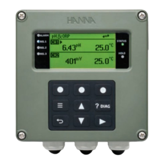
HI520
is a universal process controller intended for applications where
simultaneous measurement and control of process variables is needed.
Package contents
• HI520
controller
• Cable gland seals (1 set)
• Power cable, 3 m (9.84') long
• Instrument quality certificate and quick reference guide
Note: Save all packing material. Any damaged or defective item must
be returned in its original packing material with the supplied accessories.
Controller models
HI520-0320
3 relays & 2 analog outputs
Main features
• Hanna Smart digital probes
• RS-485 / Modbus serial communication protocol
• Independent / sequential channel control
• Flexible function assignment for control, cleaning, Hold relays
• IP65 / NEMA 4X protection
• Wall, pipe, panel mounting kit (sold separately)
HI510-01 panel mount
HI510-03 pipe mount
Hanna is committed to developing and deploying digital solutions
with a positive impact on the environment and climate.
Hanna Instruments Inc., 584 Park East Drive, Woonsocket, RI 02895 USA
HI520 Dual-Channel Universal Process Controller
HI520-0540
5 relays & 4 analog outputs
HI510-02 wall mount
Safety precautions
• Electrical connection must be carried out by specialized personnel
only. Read safety manual instructions before connecting to power.
• Do not make electrical connections with device connected to power.
• Do not run other cables through the designated power cable gland.
• Have a disconnect switch installed in the vicinity of the instrument
to ensure electrical circuit is de-energized for installation.
Opening the enclosure
• Loosen the four screws, enough for the springs to push them out.
• Grasp the front bezel and swing open to access the two-
terminal power supply board.
Connecting to power
• Remove the blank plug and thread the cable through the power
cable gland.
• Remove the safety cover to access high voltage Terminal 1.
• Connect the probe leads to the terminal connector POWER.
Follow
lead markings for correct wiring on the supply
board. Each leads location is marked.
• Ensure the power connector is seated correctly in the power socket.
• Replace safety cover over Terminal 1.
Probe accessories (sold separately)
Saddle
Flow cell
BL120-5XX
BL120-4XX
Scan the QR code or follow the link to download the user
manual. https://manuals.hannainst.com/HI520
Quick Reference Guide
Blank plug
SIGNAL
PATH
POWER
PATH
Power cable
Immersion electrode holders
HI60501 HI60503
www.hannainst.com
Advertisement
Table of Contents

Subscribe to Our Youtube Channel
Related Manuals for Hanna Instruments HI520


Summary of Contents for Hanna Instruments HI520
- Page 1 Scan the QR code or follow the link to download the user Hanna is committed to developing and deploying digital solutions manual. https://manuals.hannainst.com/HI520 with a positive impact on the environment and climate. Hanna Instruments Inc., 584 Park East Drive, Woonsocket, RI 02895 USA www.hannainst.com...
- Page 2 (in meters) Galvanic DO Optical DO Probes are sold separately. Scan the QR code to download Please retain for future use. the user manual: QR520 12/22 Hanna Instruments Inc., 584 Park East Drive, Woonsocket, RI 02895 USA www.hannainst.com...
Need help?
Do you have a question about the HI520 and is the answer not in the manual?
Questions and answers