Hanna Instruments HI520 Instruction Manual
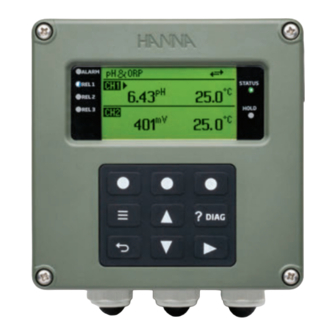
Dual-channel universal process controller
Hide thumbs
Also See for HI520:
- Instruction manual (173 pages) ,
- Quick reference manual (2 pages) ,
- Instruction manual (48 pages)

Related Manuals for Hanna Instruments HI520


Summary of Contents for Hanna Instruments HI520
- Page 1 INSTRUCTION MANUAL HI520 Dual-Channel Universal Process Controller Modbus Remote Control Hanna Instruments Inc., 584 Park East Drive, Woonsocket, RI 02895 USA www.hannainst.com...
- Page 2 All rights are reserved. Reproduction in whole or in part is prohibited without the written consent of the copyright owner, Hanna Instruments Inc., Woonsocket, Rhode Island, 02895, USA. Hanna Instruments reserves the right to modify the design, construction, or appearance of its products without advance notice.
-
Page 3: Table Of Contents
Recommendations for Users ............................42 Warranty ..................................42 General Safety Precautions & Installation Recommendations HI520 safety precautions and installation recommendations apply. Procedures and instructions detailed in this section may require special precautions to ensure the safety of the personnel performing the operations. -
Page 4: Introduction
Introduction 1. INTRODUCTION Modbus is a request‑response software protocol implemented on HI520 and intended for efficient and immediate remote industrial process control. Main Features • Allows immediate response to a problem with equipment (even from different plants) • Minimizes production downtime as mechanical issues are quickly identified •... - Page 5 Modbus Protocol Basics General query message structure Device Address Function Code Query Data Error Check Error Check Response Data Function Code Device Address • Device Address – individual client address • Function Code – type of action • Query Data Response Data –...
- Page 6 Modbus Protocol Basics Modbus functions Modbus data types • Coil (1 bit) – forces the ON/OFF state of discrete outputs (DO) or modifies mode / status of client devices. Coil is both read and write. Addresses are in the 9999 range.
- Page 7 Modbus Protocol Basics Retrieving and setting controller parameters Parameters grouped based on functionality: • read only – accessed with read inputs and read registers functions (03) • read & write – accessed with functions related to coils and holding registers Read coils (0x01) Read from 1 to 2000 maximum contiguous status of coils Function code...
- Page 8 Modbus Protocol Basics Write single coil (0x05) Write a single coil Function code 1 byte 0x05 Request Coil address 2 bytes 0 to 65535 (0 to 0xFFFF) Coil value 2 bytes 0x0000 or 0xFF00 Function code 1 byte 0x05 Normal Coil address 1 byte 0x0000 to 0xFFFF...
-
Page 9: Wiring & Controller Settings Configuration
9 Wiring & Controller Settings Configuration 3. WIRING & CONTROLLER SETTINGS CONFIGURATION 3.1. WIRING Follow the lead markings (+ positive / – negative) to ensure that output leads are correctly wired to the COMM position on the main board. Terminal Terminal - B A + - B A + - B A + COMM... - Page 10 Wiring & Controller Settings Configuration Comm Protocol (Communication Protocol) Parameter indicates supported transmission mode (Modbus RTU). Parameter Options Default Modbus Protocol Modbus RTU Modbus RTU Net Address 01 to 99 Baud Rate 9600, 19200, 38400, 57600, 115200, 256000 19200 Parity None, Even, Odd None Stop Bits 1 or 2 bits 1 bit...
-
Page 11: Operation Modes When Using Modbus
Calibration System calibration Note: Remote Control is not available. Remote operation is available. Remote Control HI520 remote control mode When not enabled, controller reverts to manual mode. Remote Control Mode must be enabled. Remote View View parameter & settings values Use Modbus function codes to view or retrieve data. -
Page 12: Modbus General Steps
Operation Modes when using Modbus 4.1. MODBUS GENERAL STEPS Prerequisite for HI520 remote operation The controller must not be in Manual, Calibration, or Local Edit Mode as these modes prevent remote operation. Steps 1. Ensure remote communication is enabled and serial communication parameters match the Modbus server. -
Page 13: Modbus Special Holding Registers
13 Operation Modes when using Modbus 4.2. MODBUS SPECIAL HOLDING REGISTERS Four special holding registers can be read and written to, regardless of operating mode, to allow a Modbus server to enter controller’s password, check status, as well as view and set remote operating modes. Address Register Size Note 40193... -
Page 14: Retrieving Controller Parameters
Operation Modes when using Modbus 4.3. RETRIEVING CONTROLLER PARAMETERS 1. Ensure HI520 is correctly configured for remote communication and RemLink or RemEdit have not timed out. ` Controller is ready for reading data. 40195 40196 Modbus Holding Registers contain status and link information that is not password protected. -
Page 15: Modbus Functions
` This confirms the controller has exited Remote Editing mode. 5. MODBUS FUNCTIONS HI520 controller’s parameters can be read or modified via Modbus functions. Parameters are grouped based on their functionality. Not all addresses are used; unused addresses are not shown. -
Page 16: Coil Registers (0Xxxx Addresses)
Coil Registers (0xxxx Addresses) 5.3. COIL REGISTERS (0XXXX ADDRESSES) The following functions support the coil registers: Decimal Name 0x01 Read coil 0x05 Write single coil 0x0F Write multiple coils Address Coil Function Address Coil Function 00001 KeyBeep 00026 Clean Schedule Tuesday Enable 00002 ErrorBeep 00027 Clean Schedule Wednesday Enable 00003 CH1 Setpoint 1 enable control 00028 Clean Schedule Thursday Enable... -
Page 17: Discrete Inputs (1Xxxx Addresses)
17 Discrete Inputs (1xxxx Addresses) 5.4. DISCRETE INPUTS (1XXXX ADDRESSES) The following function supports the discrete inputs: Decimal Name 0x02 Read input Address Coil Function Address Coil Function 10001 CH1 Setpoint 1 Overtime Alarm 10038 Smart Input Alarm Low 10002 CH1 Setpoint 2 Overtime Alarm 10039 Smart Input Disconnected 10003 CH1 Main Parameter Alarm High 10040 Smart Input Locked... -
Page 18: Input Registers (3Xxxx Addresses)
Input Registers (3xxxx Addresses) 5.5. INPUT REGISTERS (3XXXX ADDRESSES) The following function supports the Input Registers: Decimal Name 0x04 Read input register Address Parameter Size Note CH1 Main Parameter Value float Low part of float (bytes 1‑0) 30001 High part of float (bytes 3‑2) 30002 CH1 Main Parameter Eng Unit 8 bytes... - Page 19 19 Input Registers (3xxxx Addresses) Address Parameter Size Note uint8 _ t CH1 Probe Parameters No 30038 uint8 _ t CH1 Probe Measure Mode 30039 uint8 _ t CH1 Probe Measure Unit 30040 CH1 Main Parameter Name 8 bytes bytes 1‑0 30041 bytes 3‑2 30042 bytes...
- Page 20 Input Registers (3xxxx Addresses) Address Parameter Size Note CH1 Aux2 Parameter Name 8 bytes bytes 1‑0 30080 bytes 3‑2 30081 bytes 5‑4 30082 bytes 7‑6 30083 CH1 Aux2 parameter engineering unit basic Name 8 bytes bytes 1‑0 30084 bytes 3‑2 30085 bytes 5‑4 30086 bytes 7‑6...
- Page 21 21 Input Registers (3xxxx Addresses) Address Parameter Size Note = Calibration Buffer 30106 • Hanna • NIST = Measured mode (Probes measure in different parameters) DO probe • DO saturation (%DO) • DO concentration (mg/L) EC probe • Conductivity (µs, mS) • Total Dissolved Solids (ppm, ppt, mg/L, g/L) •...
- Page 22 Input Registers (3xxxx Addresses) Address Parameter Size Note uint8 _ t CH1 Probe Constant2 Resolution 30122 uint8 _ t CH1 Probe Constant2 Type 30123 CH1 Probe Constant2 Name 24 bytes bytes 1‑0 30124 bytes 3‑2 30125 bytes 5‑4 30126 bytes 7‑6 30127 bytes 9‑8 30128 bytes...
- Page 23 23 Input Registers (3xxxx Addresses) Address Parameter Size Note bytes 23‑22 30165 uint16 _ t CH1 Probe Constant5 Value 30166 uint8 _ t CH1 Probe Constant5 Resolution 30167 uint8 _ t CH1 Probe Constant5 Type 30168 CH1 Probe Constant5 Name 24 bytes bytes 1‑0 30169 bytes...
- Page 24 Input Registers (3xxxx Addresses) Address Parameter Size Note bytes 19‑18 30208 bytes 21‑20 30209 bytes 23‑22 30210 uint16 _ t CH1 Probe Constant8 Value 30211 uint8 _ t CH1 Probe Constant8 Resolution 30212 uint8 _ t CH1 Probe Constant8 Type 30213 CH1 Probe Constant8 Name 24 bytes bytes 1‑0 30214...
- Page 25 25 Input Registers (3xxxx Addresses) Address Parameter Size Note bytes 15‑14 30251 bytes 17‑16 30252 bytes 19‑18 30253 bytes 21‑20 30254 bytes 23‑22 30255 uint16 _ t CH1 Probe Constant11 Value 30256 = Incremental (–Min. Range Value ÷ Max. Range Value) = Unit DO probe •...
- Page 26 Input Registers (3xxxx Addresses) Address Parameter Size Note uint8 _ t CH1 Probe Constant11 Type 30258 = Incremental Type = Unit Type = Check Glass Impedance = Check Reference Impedance = Temperature Compensation Type = Incremental Temperature Type = Incremental Temperature Offset Type = Incremental Calibration Timeout = Incremental Resolution Type = Incremental buffer Type...
- Page 27 27 Input Registers (3xxxx Addresses) Address Parameter Size Note = Calibration Buffer 30273 • Hanna • NIST = Measured mode (Probes measure in different parameters) DO probe • DO saturation (%DO) • DO concentration (mg/L) EC probe • Conductivity (µs, mS) • Total Dissolved Solids (ppm, ppt, mg/L, g/L) •...
- Page 28 Input Registers (3xxxx Addresses) Address Parameter Size Note uint8 _ t CH2 Probe Constant2 Resolution 30289 uint8 _ t CH2 Probe Constant2 Type 30290 CH2 Probe Constant2 Name 24 bytes bytes 1‑0 30291 bytes 3‑2 30292 bytes 5‑4 30293 bytes 7‑6 30294 bytes 9‑8 30295 bytes...
- Page 29 29 Input Registers (3xxxx Addresses) Address Parameter Size Note bytes 23‑22 30332 uint16 _ t CH2 Probe Constant5 Value 30333 uint8 _ t CH2 Probe Constant5 Resolution 30334 uint8 _ t CH2 Probe Constant5 Type 30335 CH2 Probe Constant5 Name 24 bytes bytes 1‑0 30336 bytes...
- Page 30 Input Registers (3xxxx Addresses) Address Parameter Size Note bytes 19‑18 30375 bytes 21‑20 30376 bytes 23‑22 30377 uint16 _ t CH2 Probe Constant8 Value 30378 uint8 _ t CH2 Probe Constant8 Resolution 30379 uint8 _ t CH2 Probe Constant8 Type 30380 CH2 Probe Constant8 Name 24 bytes bytes 1‑0 30381...
- Page 31 31 Input Registers (3xxxx Addresses) Address Parameter Size Note bytes 15‑14 30418 bytes 17‑16 30419 bytes 19‑18 30420 bytes 21‑20 30421 bytes 23‑22 30422 uint16 _ t CH2 Probe Constant11 Value 30423 = Incremental (–Min. Range Value ÷ Max. Range Value) = Unit DO probe •...
-
Page 32: Holding Registers (4Xxxx Addresses)
Holding Registers (4xxxx Addresses) Address Parameter Size Note uint8 _ t CH2 Probe Constant11 Type 30425 = Incremental Type = Unit Type = Check Glass Impedance = Check Reference Impedance = Temperature Compensation Type = Incremental Temperature Type = Incremental Temperature Offset Type = Incremental Calibration Timeout = Incremental Resolution Type = Incremental buffer Type... - Page 33 33 Holding Registers (4xxxx Addresses) Min. Max. Default Address Register Function Size Details Value Value Value uint8 _ t 40001 Log interval = 10 s, = 30 s, = 1 min, = 2 min, = 5 min, = 10 min, = 15 min, = 30 min, = 60 min, = 120 min,...
- Page 34 Holding Registers (4xxxx Addresses) Min. Max. Default Address Register Function Size Details Value Value Value uint16 _ t 40022 Cleaning post wash time [seconds] uint16 _ t 40023 Cleaning Recovery time [seconds] uint8 _ t 40024 Cleaning Wash Cycles uint8 _ t 40025 Cleaning Rinse only cycles time to start hour uint8 _ t 40026 Cleaning Schedule 1 uint8 _ t...
- Page 35 35 Holding Registers (4xxxx Addresses) Min. Max. Default Address Register Function Size Details Value Value Value uint8 _ t 40052 AnOut1 22 mA on Hold option = “Disabled” = “Enabled” 40053 AnOut1 parameter Value for float Low part of float maximum output (bytes 1‑0) 40054 High part of float (bytes 3‑2)
- Page 36 Holding Registers (4xxxx Addresses) Min. Max. Default Address Register Function Size Details Value Value Value uint8 _ t 40073 AnOut3 parameter to follow = Ctrl SetP1 = Ctrl SetP2 = Main Param. = Temper. Param. = Auxiliary Param. uint8 _ t 40074 AnOut3 mA range = “0‑20 mA”...
- Page 37 37 Holding Registers (4xxxx Addresses) Min. Max. Default Address Register Function Size Details Value Value Value 40094 High part of float (bytes 3‑2) uint8 _ t 40097 CH1 Setpoint 1 parameter No. = main parameter = temperature uint8 _ t 40098 CH1 Setpoint 1 status = disabled = active uint8 _ t...
- Page 38 Holding Registers (4xxxx Addresses) Min. Max. Default Address Register Function Size Details Value Value Value 40121 CH1 Setpoint 2 deviation float Parameter Parameter Parameter Low part of float dependent dependent dependent (bytes 1‑0) 40122 High part of float (bytes 3‑2) 40123 CH1 Setpoint 2 hysteresis float Parameter Parameter...
- Page 39 39 Holding Registers (4xxxx Addresses) Min. Max. Default Address Register Function Size Details Value Value Value uint16 _ t 40146 CH2 Setpoint 2 minim OnTime [seconds] 40147 CH2 Setpoint 2 Value float Low limit High Limit Param. default Low part of float parameter parameter control (bytes 1‑0)
- Page 40 Holding Registers (4xxxx Addresses) Min. Max. Default Address Register Function Size Details Value Value Value 40176 High part of float (bytes 3‑2) uint8 _ t 40177 CH2 Main Param. Alarm High Enable = Disable = Enable uint8 _ t 40178 CH2 Main Param. Alarm Low Enable = Disable = Enable uint16 _ t...
- Page 41 41 Holding Registers (4xxxx Addresses) Min. Max. Default Address Register Function Size Details Value Value Value uint32 _ t 40196 Reset Controller status bytes 1‑0 = R/W Controller setup updated = R/W Chan1 calibration updated = R/W Chan2 calibration updated = RO‑ Chan1 probe update parameters = R/W ‑...
-
Page 42: Certification
If the repair is not covered by the warranty, you will be notified of the charges incurred. If the instrument is to be returned to Hanna Instruments, first obtain a Returned Goods Authorization (RGA) number from the Technical Service department and then send it with shipping costs prepaid.
Need help?
Do you have a question about the HI520 and is the answer not in the manual?
Questions and answers