
Subscribe to Our Youtube Channel
Related Manuals for Hanna Instruments HI 8001


Summary of Contents for Hanna Instruments HI 8001
- Page 1 Installation Manual for technical personnel only HI 8001 and HI 8002 Agricare-Fertigation Controller w w w. h a n n a i n s t . c o m...
-
Page 2: Table Of Contents
All rights are reserved. Reproduction in whole or in part is prohibited without the written consent of the copyright owner, Hanna Instruments Inc. Hanna Instruments reserves the right to modify the design, construction or appearance of its products without advance notice. -
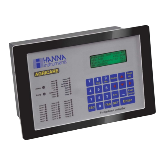
Page 3: Controller Hardware Presentation
1 CONTROLLER HARDWARE PRESENTATION 1.1 ELECTRICAL SPECIFICA 1.1 ELECTRICAL SPECIFICA 1.1 ELECTRICAL SPECIFICATIONS TIONS TIONS TIONS 1.1 ELECTRICAL SPECIFICA 1.1 ELECTRICAL SPECIFICA TIONS p n I s t u p u s y l p . c . 0 6 / c a V i x u a i l... -
Page 4: Inputs Outputs Description
1.2.1 Analog Inputs 1.2.1 Analog Inputs The main board of HI 8001 and HI 8002 controllers have on the right side eight inputs dedicated for the standard analog signals: seven of the 4-20mA type and one of the 0-2V type. - Page 5 HI 8001/2. The serial cable is Hanna serial cable type. To allow our users access to the latest version of Hanna Instruments PC compatible software, we made the products available for download at http://software.hannainst.com. Select the product code and click Download Now.
-
Page 6: Controller Installation
1.2.8 R 1.2.8 R 1.2.8 R 1.2.8 R 1.2.8 Relay outputs elay outputs elay outputs elay outputs elay outputs The other digital outputs are of relay type and also support 10A. For this output type only the NO and COMMON terminals are accessible on the connector . Twenty-four of these outputs are on the extension board and can be optional. -
Page 7: Connections & Wiring
2.2 CONNECTIONS & WIRING 2.2 CONNECTIONS & WIRING 2.2 CONNECTIONS & WIRING 2.2 CONNECTIONS & WIRING 2.2 CONNECTIONS & WIRING 2.2.1 Main power supply connection 2.2.1 Main power supply connection 2.2.1 Main power supply connection 2.2.1 Main power supply connection 2.2.1 Main power supply connection The main power should be connected to the J1 connector on the main board as in the next figure. - Page 8 2.2.4 Analog input connections 2.2.4 Analog input connections 2.2.4 Analog input connections 2.2.4 Analog input connections 2.2.4 Analog input connections The pH, EC and solar radiation sensors have be connected to the analog inputs through the transmit- ters, that have 4-20mA (source current type) outputs and 0-2V (solar radiation). The Hanna transmitters that can be used are HI98143-22 (1 pH, 1 EC).
- Page 9 Filter schematic The HI 8001 (2) controller has the programs to clean the filters. This operation is done by the four valves that are commanded alternatively two by two like in the schematic. The controller provides a mechanical contact that is switched ON/OFF periodically and it can be used in the installation to control the external relay (see in the appendix).
-
Page 10: Controller Start-Up
TION TION The HI 8001 (2) controller has many facilities that allow the user to configure it according to his/here purposes. To demonstrate the controller functionality you can run a lot of program setting types, depending on the imagination. In this section we present below a controller programming sample... - Page 11 Make the following settings: Program 1 Program 1 Program 1 Program 1 Program 1 Irrig ctrl mode (S53): Sets time mode Active Timetable (S31): sets a valid range for the current day Set priority (S33): sets 1 priority sect/group 4 Start conditions (S34): sets Time condition Y Set start time (S35): sets three start hours ex: xx: 00, xx: 03, xx: 06 Set program repeats (S36): sets 0...
- Page 12 Program 4 Program 4 Program 4 Program 4 Program 4 Irrig ctrl mode (S53): Sets time mode Active Timetable (S31): sets a valid range for the current day Set priority (S33): sets 1 priority Start conditions (S34): sets External tank 04 Set program repeats (S36): sets 0 Pre/post Irrig.
- Page 13 If the repair is not covered by the warranty, you will be notified of the charges incurred. If the instrument is to be returned to Hanna Instruments, first obtain a Returned Goods Authorization number from the Technical Service department and then send it with shipping costs prepaid. When shipping any...
-
Page 14: Appendix 1 - Electrical Diagrams
3 APPENDIX - ELECTRICAL DIAGRAMS POWER EXTENSION MAIN BOARD BOARD BOARD 220 Vac 220 Vac RS 232 200 mA COM OUT 3 NC ALARM COM OUT 3 NO ALARM TEMP BREAK VALVE 9 COND STOP COM OUT AL VALVE 10 IRIG COUNT VALVE 11 DIF PRES 1... - Page 15 DIGITAL OUTPUT...
- Page 16 ISTL8001 06/19...
Need help?
Do you have a question about the HI 8001 and is the answer not in the manual?
Questions and answers