Hanna Instruments HI520 Instruction Manual
Dual‑channel universal process controller multiparameter platform
Hide thumbs
Also See for HI520:
- Instruction manual (42 pages) ,
- Quick reference manual (2 pages) ,
- Instruction manual (48 pages)

Related Manuals for Hanna Instruments HI520


Summary of Contents for Hanna Instruments HI520
- Page 1 INSTRUCTION MANUAL HI520 Dual‑Channel Universal Process Controller Multiparameter Platform Hanna Instruments Inc., 584 Park East Drive, Woonsocket, RI 02895 USA www.hannainst.com...
- Page 2 All rights are reserved. Reproduction in whole or in part is prohibited without the written consent of the copyright owner, Hanna Instruments Inc., Woonsocket, Rhode Island, 02895, USA. Hanna Instruments reserves the right to modify the design, construction, or appearance of its products without advance notice.
-
Page 3: Table Of Contents
19.6. Stop Cleaning ........105 1.1. Preliminary Examination ....... 4 1.2. Safety Measures .......... 4 20. HI520 Events Management System ......107 1.3. General Description & Intended Use ....5 21. Measuring with pH & ORP Probes ......114 2. Specifications ............8 21.1. -
Page 4: Introduction
1.1. PRELIMINARY EXAMINATION Remove the instrument and accessories from the packaging and examine it carefully. For further assistance, please contact your local Hanna Instruments office or email us at tech@hannainst.com. Each unit is supplied with: • Power cable, 3 m (9.84’) long •... -
Page 5: General Description & Intended Use
Introduction 1.3. GENERAL DESCRIPTION & INTENDED USE ® HI520 of the first dual‑input process controller Hanna Instruments that accepts virtually any combination of compatible probes. Designed to adapt to unique process control requirements, HI520 operates a control‑loop system whereby users have the option to run channel control independently or configure to be triggered sequentially upon reaching the other channel's set point(s) (1, 2, or both). - Page 6 Introduction Main Features • Smart probes with RS‑485 connection. Automatic probe recognition and upload of Process input configuration calibration, and measurement data. User interface • Easily navigable main menu and submenus • Two or four, depending on the controller model Analog Outputs ` 0 –...
- Page 7 • Log files can be uploaded to a USB flash drive via USB‑C port • pH Up to three‑points standard calibration with selection from two buffer groups: ` Hanna Instruments: 1.68, 4.01, 7.01, 10.01, 12.45 pH ` NIST: 1.68, 4.01, 6.86, 9.18, 12.45 pH • Conductivity Up to two‑points user calibration with selectable calibration points:...
-
Page 8: Specifications
Specifications 2. SPECIFICATIONS 2.1. CONTROLLER Model Relays Analog Outputs HI520‑0320 HI520‑0540 2.1.1. Specifications • pH HI1006‑18 (LT, PTFE junction) HI1016‑18 (LT, ceramic junction) HI1006‑38 (HT, PTFE junction) HI1016‑38 (HT, ceramic junction) HI1006‑48 (HF, PTFE junction) HI1016‑48 (HF, ceramic junction) HI1026‑1803 (meat applications only) HI1126‑1805... - Page 9 9 Specifications 2 or 4 independent outputs 0 – 22 mA configurable as: Analog outputs ` 0 – 20 mA ` 4 – 20 mA ` 22 mA as alarm signal Analog output accuracy ±0.2 % f.s. • RS‑485 serial port for remote monitoring and control (Modbus) Digital communication •...
-
Page 10: Supported Probe Series Configurations
Specifications 2.2. SUPPORTED PROBE SERIES CONFIGURATIONS – HI10 PolyTetraFluoro‑Ethylene (PTFE) junction Ceramic junction Low Temperature (LT) glass sensor, titanium matching pin 0.00 to 12.00 pH –5.0 to 80.0 °C (23.0 to 176.0 °F) High Temperature (HT) glass sensor, titanium matching pin 0.00 to 14.00 pH 0.0 to 100.0 °C (32.0 to 212.0 °F) Fluoride‑resistant (HF) glass sensor, titanium matching pin... -
Page 11: Controller Basics
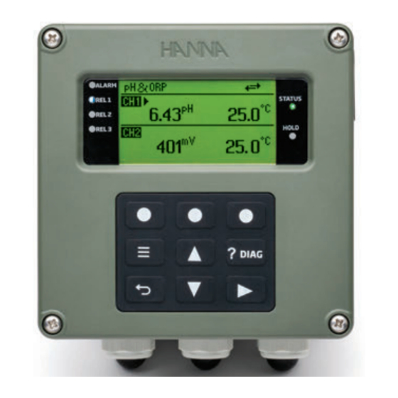
11 Controller Basics 3. CONTROLLER BASICS 3.1. FRONT PANEL • The front panel includes a graphic display and keypad with tactile feedback • Two LEDs, ALARM and STATUS, indicate alarm and status conditions • HOLD LED lights up yellow indicating controller HOLD status •... - Page 12 Controller Basics 3.1.1. LCD Display Functions Screenshots below show typical examples of measurement screen areas for readings taken with two wired probes. CH1 displays pH measurement data and CH2 displays conductivity (EC) measurement data. Notes: • Units for measured value change, depending on wired probe. •...
-
Page 13: Contextual Help
Perform the functions displayed on the bottom of the display screen. Used to set or modify parameters values or to access, export, or delete log files. 3.2. CONTEXTUAL HELP HI520 offers an interactive contextual help mode that assists the user at any time. • Press (diagnostic key) to access the help screen. -
Page 14: Usb-C Port
Controller Basics Symbol Example Function Measure pH Displayed next to the reading (e.g. temperature reading), 7.37 Ж indicates Alarm High on the parameter. °C 50.1 Measure pH Displayed next to the reading (e.g. temperature reading), 7.43 З indicates Alarm Low on the parameter. °C Fatal error screen. -
Page 15: Measurement Screens
15 Controller Basics 3.5. MEASUREMENT SCREENS Measure is the normal operating mode. With probe connected, controller automatically detects probe type. Screenshots below display sensor measurement data – value, unit, temperature compensation type – taken with pH, ORP, Conductivity, and Dissolved Oxygen probes. Connected probe Measure type Dual &... - Page 16 Controller Basics 3.5.1. Selecting Measure Channel The default display mode is dual‑channel view. The controller remembers last selected mode upon restart. • Press the keys to select channel. The Б symbol indicates active channel. pH & pH & °C 6.43 25.0 6.43 STD.
-
Page 17: Installation & Controller Start-Up
17 Installation & Controller Start-Up 4. INSTALLATION & CONTROLLER START‑UP 4.1. INSTALLATION HARDWARE 4.1.1. Guidelines • The controller is suitable for outdoor use, but installation in direct sunlight or in areas of extreme temperature is not recommended. • Based on controller specifications, installation thermal conditions are in the –20 to 50 °C (–4 to 122 °F) range. •... - Page 18 Wall‑Mount Panel Thickness, Mounting Bolts & Slots Dimensions The minimum depth required by a unit fastened to a 12 mm (0.5“) mounting plate is 163 mm (6.4”). 163 mm [ 6.4” ] Figure 6: HI520 Controller Fastened to Wall‑Mount Panel...
- Page 19 19 Installation & Controller Start-Up Wall‑Mount Hardware & Steps The controller can be mounted on a wall using a Wall‑Mount panel that can be fixed either horizontally or vertically. Use the Wall‑Mount panel with appropriate hardware. See table, description column, for details. The mounting kit does not include the fasteners required for attaching the Wall‑Mount panel to the wall. Fasteners type and length selection must be based on wall type i.e.
- Page 20 Installation & Controller Start-Up To wall mount the controller: 1. Select the position desired for the controller and following the dimensions indicated in Figure 5, drill the holes required for attaching the Wall‑Mount panel to the surface. The drill size depends on the fasteners dimension required by wall type and thickness.
- Page 21 21 Installation & Controller Start-Up Panel‑Mount Hardware & Steps The controller can be mounted in a panel using two brackets and appropriate, user‑supplied hardware that includes external gasket and several types of screws. See table, description column, for details. Figure 10: Panel‑Mount Schematic Panel‑Mount Hardware Label Description...
- Page 22 Installation & Controller Start-Up To mount the controller on a panel: 1. Select the position desired for the controller on the panel, and make the cutout following dimensions indicated in Figure 9. Smooth the cutout edges so as not to damage the gasket or to scratch the controller during assembly.
- Page 23 23 Installation & Controller Start-Up 4.1.4. Pipe Mount Pipe‑Mount Hardware & Steps The controller can be mounted vertically or horizontally on a pipe. Use a mount plate and U‑Bolts together with supplied hardware that includes hex nuts and several types of screws. See table, description column, for details. Figure 12: Pipe‑Mount Schematic Pipe‑Mount Hardware...
-
Page 24: Wiring
Installation & Controller Start-Up Figure 13: Vertical & Horizontal Pipe Mount To mount the controller on a pipe: 1. Fasten mounting plate to controller, using hardware detailed in the hardware table. 2. Measure the pipe diameter and select the appropriate U‑Bolt size. The mounting kit includes three U‑Bolt sizes, for pipe size from ¾” to 2 ½”. 3. - Page 25 25 Installation & Controller Start-Up SIGNAL PATH POWER PATH Power cable Figure 14: Conduit Openings Probe 2 Probe 1 or remote communication Analog Outputs & Digital Inputs Alarm relays Control relays Power cable Venting element Assembly drawing of an exposed cable gland below. The seal is entering from the external part and the parts are shown on each side of the enclosure wall.
- Page 26 To open the enclosure, loosen the four captive screws enough for the springs to push them out. Selection of mounting location should be such that allows the front panel to swing open fully and that there is adequate room around the mounting location for wire routing. Figure 16: HI520 Enclosure Opened Figure 17:...
- Page 27 27 Installation & Controller Start-Up 4.2.4. Wiring the Controller Easy access to HI520 installation terminals − push in and plug out − enables quick wiring. • High voltage connections (Terminal 1) • Low voltage connections (Terminal 2) ` Power ` COMM (RS‑485) ` Alarm...
- Page 28 Installation & Controller Start-Up Terminal 1 Terminal 2 ALARM CONDITION OR METER OFF COMM 100mA ALARM RELAY NO ALARM PROBE 1 100mA 5-30V RELAY 1 DIGITAL RELAY 2 INPUTS 5-30V RELAY 3 RELAY 4 RELAY 5 0 - 20 mA OUT / AO 1 4 - 20 mA OUT 0 - 20 mA OUT / AO 2...
- Page 29 29 Installation & Controller Start-Up Fail Safe Alarm Feature The controller is equipped with the Fail Safe alarm feature to protect the process against critical errors arising from power interruptions, power surges and human errors. The Fail Safe alarm feature resolves these predicaments on two fronts: hardware and software. Hardware To eliminate problems of blackout and line failure, the alarm function operates in a “Normally Closed”...
- Page 30 Keep connection between COMM terminals and cable trunk as short as possible. Recommended use of 120 Ω / 0.5 W End Of Line Resistor (EOLR), if HI520 is the last device connected to a RS‑485 Bus cable. 4. Feed excess cable through the cable gland before tightening nut.
-
Page 31: Starting-Up The Controller
4. Feed excess cable through the cable gland before tightening nut. 4.3. STARTING‑UP THE CONTROLLER At start‑up, with probe(s) wired correctly, while the controller performs internal checks, the display will show the Hanna Instruments logo, controller name, and firmware version. HI520 Process Controller Date: 2023-02-07 V1.00... -
Page 32: Controller Setup - Menu Structure
Controller Setup – Menu Structure 5. CONTROLLER SETUP – MENU STRUCTURE The MENU key – – is used to access menus for programming control functions and calibrating the controller. • Press from the live reading display to access the top‑level Menu items. • Press to navigate items. -
Page 33: Channel
33 Channel Manu item Screenshot Function LOG RECALL Access logged data and transfer files to USB stick Configure or view general settings (e.g. log interval, GENERAL password, date and time, language selection, setting RS‑485 communication parameters, setting controller ID) 6. CHANNEL When Channel is selected Disable (Enable), Setup, CAL virtual keys are visible. -
Page 34: Probe Settings, General Parameters
Channel 6.2. PROBE SETTINGS, GENERAL PARAMETERS This section groups configurable Probe Settings items common to all wired probes regardless of measured parameter as well as probe information details. Calibration timeout, Temp. source, Manual Temperature Value, setting the temperature Offset value follow the same steps regardless of wired parameter. - Page 35 35 Channel Temperature Calibration Steps 1. Place the probe and a reference thermometer (with 0.1 ° resolution) into a stirred container of water. 2. Observe the temperature on display until it stops changing. This may take several minutes. 3. Calculate the Temp.Offset (i.e. reference thermometer temperature minus probe temperature). 4.
-
Page 36: Process) Control & Alarm Settings
6.3. (PROCESS) CONTROL SETTINGS & ALARM SETTINGS Control and Alarm Settings, part of process‑control system, are grouped under Channel menu item. HI520 operates a control‑loop system whereby users have the option to run channel control independently (CH1 or CH2) or configure to be triggered sequentially upon reaching the other channel's set point(s) (1, 2, or both). - Page 37 37 Channel Parameter Option: see 2.2 Supported Probe Series Configurations for supported parameters Parameter, measurement units, minimum and maximum probe values, Hysteresis, Deviation, Dead Band values, Control Period, Reset Time, Rate Time, Dead Band Gain depend on configured Control Mode option (i.e. ON/ OFF, Proportional, PID) in Probe Settings submenu.
- Page 38 Channel • Press Select to save. • After selecting Mode, press Setup. Setup for ON/OFF control • Press Setup for the options submenu to be displayed. • Press the keys to move between Mode and Hysteresis. • Select Mode and press the virtual keys to select ON/OFF Low or ON/OFF High. •...
- Page 39 39 Channel • Select Mode and press the virtual keys to select Prop. High or Prop. Low. • Press the key to select Deviation. • With Deviation highlighted, press Set. The present value will blink permitting editing using the keys. Press CFM to save. •...
- Page 40 Channel Prop. control. Editable default and boundary values. Control parameters Measured parameter Default Minimum Maximum * 0.20 pH 0.00 pH 5 % of measured 10 mV 0 mV range but no more Dead Band than Deviation value 400.0 μS 0.000 μS divided by 5 20 %Sat 0.0 %Sat...
- Page 41 41 Channel • With Reset Time highlighted, press Set. The present value will blink permitting editing, within the boundary values, using the keys. The default value disables the Integrative contribution. • Press the key to select Rate Time. • With Rate Time highlighted, press Set. The present value will blink permitting editing, within the boundary values, using the keys.
- Page 42 Channel PID control. Editable default and boundary values. Control parameters Measured parameter Default Minimum Maximum Rate Time 0 seconds 0 seconds 16:40 hours 0.20 pH 0.00 pH 5 % of measured 10 mV 0 mV range but no more Dead Band than Deviation 400.0 μS 0.000 μS...
- Page 43 43 Channel Minimum ON Time (Setpoint must be enabled first) Option: 1 to 10 seconds Allows users to control the speed of the relay status change when previously set conditions are met. This timer prevents the relay and connected device from “chattering” by forcing a minimum on and off time. The flashing of the selected value indicates that it can be modified by using the keys.
- Page 44 Channel Parameter Option: see 2.2 Supported Probe Series Configurations for all available parameters. With Parameter selected, press the corresponding virtual key to toggle between options. Alarm High Enabled Option: Enabled, Disabled • With Alarm High Enabled selected, press the corresponding virtual key to toggle between enable or disable options.
- Page 45 45 Channel Alarm Low (Alarm Low Enabled must be checked first) Allows users to set the lower‑limit value for the alarm. • To modify the value, with Alarm Low selected, press Set. The blinking of the selected value indicates that value can be modified by using the keys.
-
Page 46: Hold Mode
Hold Mode 7. HOLD MODE Note: Setup selections do not change if a new parameter probe is used on controller. When Hold Mode is selected, Man. On or Man Off virtual keys are visible. 7.1. TURNING ON MANUAL HOLD The Hold Mode submenu is used to turn on or off a manual Hold. It can also be used to configure a remote hold feature that uses a digital Input Trigger. - Page 47 47 Hold Mode Hold Input Hold mode can be triggered using external trigger inputs. This is a read‑only parameter that indicates what Inputs are configured to initiate Hold mode. If an input is selected, the selected input is displayed. • To change the input assignment for Hold Input, return to the top level Menu structure and select Inputs. •...
-
Page 48: Math Channel
Math Channel 8. MATH CHANNEL Match channel dispalys the mathematical result of the measurement between two probes with identical measurement configuration and unit. Channel can only be configured when: • Both probes are connected and initialized • Both probes are of the same type (pH, ORP, EC, DO) have same Measure Mode, and Measurement Unit Notes: Channel data is not logged in the data Log files. -
Page 49: Math Channel Measurement
2.543 199.4 212.9 9. SEQUENTIAL CONTROL HI520 operates a control‑loop system whereby users have the option to run channel control independently or configure to be triggered sequentially upon reaching the other channel's set point(s) (1, 2, or both). Navigation • From Main Menu, use the keys to select Sequential Control. -
Page 50: Relays
• Press Modify to select the relay operating mode. Multiple relays can be allocated to the same function. Note: HI520-0320 has 3 relays, 2 Analog Outputs (AO) & HI520-0540 has 5 relays, 4 Analog Outputs (AO). -
Page 51: Analog Outputs
51 Outputs 10.2. ANALOG OUTPUTS Note: Controller model determines the number of relays and analogs. Navigation • From Analog Outputs, press Setup. • Press the keys to navigate between parameters. Setup Setup Enable Enable • Press the key to return to the menu without saving. •... - Page 52 Outputs Parameter Option: CtrlSetP1, CtrlSetP2, probe parameter reading, Temperature With Parameter selected, press Modify and select the parameter from the available options. Press Select to save. When analog output is assigned to CtrlSetPx, it will follow specific Set point control output.
- Page 53 53 Outputs Output Range Option: 0 ‑20 mA, 4 ‑20 mA With Output Range selected, press the corresponding virtual key, to toggle mA output range: 0 ‑20 mA or 4 ‑20 mA. 0 mA or 4 mA Value Option: measured parameter, CtrlSetP1 or CtrlSetP2 •...
-
Page 54: Inputs
Inputs Fixed Value • With Fixed Value selected, press Set. The value will flash indicating it can be modified. • Press the keys to increase or decrease the value. Press CFM to save the value. • Press the key to return to the menu. Out 22 mA ‑... - Page 55 55 Inputs For modifying the operating mode for either input please follow the four‑step procedure below: 1. With Input 1 (or Input 2) selected, press Setup. 2. Use the keys to navigate between options. 3. Press Modify, for the Function drop‑down list to display. 4.
-
Page 56: Cleaning
Cleaning 12. CLEANING Note: Setup selections do not change if a new parameter probe is wired. The cleaning menu is used to program a time‑controlled cleaning function that uses the configured relays to activate valves, pumps or compressed air to automate probe cleaning. Two types of cleaning may be programed: Simple and Advanced. - Page 57 57 Cleaning • With Cleaning selected, press Setup to enter screen. Setup Enable • At prompt, enter the passcode. • At prompt, press YES to place unit in HOLD. • Enabled* option has to be active (check mark displayed) for the rest of the configurable parameters to be modified.
- Page 58 Cleaning Int. Trigger Option: Disabled, Timer, Schedule • With Int. Trigger selected, press Modify for the drop‑down options list to be displayed. • Use the keys to scroll between options. • Press Select to save option. When set on Timer, cleaning cycle will proceed following the time period set in the parameter Cleaning Interval. Schedule If Int.
-
Page 59: Advanced Cleaning
59 Cleaning 12.1. ADVANCED CLEANING • With item selected, press Set to modify. • Use the keys to modify the flashing digit. Press CFM to save. Item Option Screenshot Pre‑wash rinse Time 5 to 300 seconds Wash Time 5 to 300 seconds Post‑wash rinse Time 5 to 999 seconds Wash cycles No. -
Page 60: Simple Cleaning
Technical Menu 12.2. SIMPLE CLEANING • With item selected, press Set to modify. • Use the keys to modify the flashing digit. • Press CFM to save. Item Option Screenshot Rinse Time 5 to 300 seconds Recovery Time 5 to 120 seconds Rinse Relay Displays allocated rinse relay Note: Controller validates configured Setup when attempting to exit Menu and directs the user to any invalid... -
Page 61: Pressure Calibration
61 Technical Menu 13.1. PRESSURE CALIBRATION Repeated calibrations may be performed and the offset is added (within ±100 mmHg limit) to the previous calibration. Use a hand held meter to determine the current pressure value. Procedure 1. Press CAL to enter calibration mode. At prompt, with the password enabled, input the passcode. -
Page 62: Analog Output Calibration
Technical Menu 13.2. ANALOG OUTPUT CALIBRATION Option: range from 4 mA to 20 mA Procedure 1. Press Setup to enter Analog Output calibration screen. 2. At prompt, with the password enabled, input the passcode. At prompt, select YES to place the unit in HOLD. 3. -
Page 63: Manual Mode
63 Manual Mode 14. MANUAL MODE When Manual Mode is selected, Setup is visible. Select Setup to open up Relays (with their configured function) and Analog Outputs submenu structure. Setup Enable When relays are turned to on, it can manually test the relay connection and operation (relay contact opening and closing) and also the operation of the associated equipment, and is a useful feature to prime a dosing pump for example. -
Page 64: Log Recall
Log Recall 15. LOG RECALL Select Log Recall item to open up measurement Log files and Event logs submenu. 15.1. MEASUREMENT LOG FILES The readings for each measurement are automatically logged at configured time intervals. A new log is started each time the instrument is calibrated or reconfigured. Logged data include measured parameter and temperature values, last calibration data, setup configuration that includes Alarm and Control Setpoints, controller and probe FW. - Page 65 • The exported logs will be in a folder named HI520‑xxxx (where x are the controller ID) Note: Do not remove the USB flash drive during the file transfer. If an error occurs during transfer, “Error while transferring”...
-
Page 66: Event Log & Event Log Types
Log Recall Delete Logged Data To delete logged files: • Use the keys to select the option and press CFM. A warning screen is displayed asking for confirmation. • Press Yes to confirm or No to return to previous screen. Note: It is recommended to export log files before deleting the files. 15.2. - Page 67 67 Log Recall Manufacturing error Probe disconnected Instrument error Alarms, Warnings Alarms on measured parameter (outside range limit) Control Alarm Control Warning...
- Page 68 Log Recall 15.2.1.2. Calibration events User calibration Process calibration 15.2.1.3. Cleaning events Cleaning 15.2.1.4. Configuration changes Hold Manual Mode Firmware update Setup update...
- Page 69 15.2.1.5. Probe specific, HI7640‑50 only ODO Cap Error HI520 Log Event Codes & Assigned Parameters HI520 operates an event logging system whereby when setting new parameter values, a Setup event and event code are generated. Log event stores the Setup event code and both new and previous values.
- Page 70 Log Recall Code Setup Parameter Code Setup Parameter 48 CH2 Set point 2 value 81 CH1 Main parameter, Alarm Low enable 49 CH1 Set point 1 control mode 82 CH1 Temperature parameter, Alarm Low enable 50 CH1 Set point 2 control mode 83 CH2 Main parameter, Alarm Low enable 51 CH2 Set point 1 control mode 84 CH2 Temperature parameter, Alarm Low enable...
- Page 71 71 Log Recall Code Setup Parameter Code Setup Parameter 141 Cleaning schedule interval 1, enabled 195 Analog out 1, output range 142 Cleaning schedule interval 2, enabled 196 Analog out 2, output range 143 Cleaning schedule interval 3, enabled 197 Analog out 3, output range 144 Schedule day, Monday 198 Analog out 4, output range 145 Schedule day, Tuesday...
- Page 72 Log Recall To exemplify how the log event system works: For Setup event code 21 Set point 1 status; with old value 0 (disabled) and new value 1 (Enabled) For Setup event code 22 Set point 2 status; with old value 22 (disabled) and new value 2 (Enabled) For Setup event code 34 Set point 2 parameter;...
-
Page 73: General Settings
73 General Settings 16. GENERAL SETTINGS Navigation • With item selected, press Setup to enter screen. Setup Enable • Use the keys to navigate. • Press the key to return to the menu without saving. • At the prompt, enter the passcode. •... - Page 74 General Settings LCD Backlight Option: 0 to 100 % • With item selected, press Set to open for the horizontal scroll bar that is used to adjust the backlight to display. • Press the keys to increase or decrease the value (keep the key pressed to fast‑forward). •...
- Page 75 75 General Settings Date Option: year / month / day • With item selected, press Set to modify. • With selected value flashing, press the key to navigate to the right between year /month / day. • Press the keys to increase or decrease the value (keep the key pressed to fast‑forward). •...
- Page 76 General Settings Decimal Option: “.” & “,” This option is a field separator for Log files. It may be set as comma “,” or full stop “.”depending upon region preferences. • With item selected, press the corresponding virtual key to toggle between options. Temperature Unit Option: Celsius (°C), Fahrenheit (°F) With item selected, press the corresponding virtual key to toggle between options.
- Page 77 77 General Settings Controller Password Option: 00000 to 99999 • With item selected, press Modify for the password input screen. • Press the key to increment the digit (displayed flashing) and the key to decrement. • Press CFM, to save. • Press the key to navigate right between digits.
- Page 78 2. Ignore prompt to enter new password and press Disable. The password is automatically disabled. Note: If the password is entered incorrectly five times, users will require assistance from Hanna Instruments service team. Controller ID Option: 0000 to 9999 •...
- Page 79 79 General Settings Comm Protocol (Communication Protocol) Option: Modbus RTU Read‑only parameter that indicates supported remote communication mode. With protocol selected, press Setup to start configuring. Configurable Comunication Protocol Parameters Net Address Option: 01 to 99 This option allows the user to set the controller’s Modbus address. •...
- Page 80 General Settings Stop Bits Option: 1, 2 This option allows the user to set stop bit option based on the stop bit of the connected device. • With Stop Bits selected, press Modify for the drop‑down list to display. • Use the keys to navigate between options.
- Page 81 81 General Settings Startup Delay Option: 1 to 30 minutes Startup Delay is a timer used to prevent Control functions (relays or outputs configured for measurement or temperature) from functioning during controller startup. • With item selected, press Set to modify the time. •...
-
Page 82: Functioning Modes & Process Variables
Functioning Modes & Process Variables 17. FUNCTIONING MODES & PROCESS VARIABLES... - Page 83 83 Functioning Modes & Process Variables Default values Probe type Controller setting Temperature Alarm High Probe maximum range Alarm Low Probe minimum range DO _ Conc: 8.26 mg/L sal %: 200 % Set point 8.00 pH 500 mV 25 °C (77 °F) DO _ Sat:100 % EC: 10.00 mS/cm Hysteresis for 1.00 pH 50 mV...
-
Page 84: Control Modes & Algorithms
This section describes the controller behavior with a pH smart probe. It presents a similar behavior with other smart probes. There are three control algorithms implemented in HI520; and each algorithm has both specific and common settings. The common settings – overtime & minimum on time – affect control output after the specific algorithm settings and rules are evaluated. - Page 85 85 Control Modes & Algorithms Navigation: • Press the from the Measure mode. • Select Setup from Channel. • Select Setup with Control Settings highlighted. • Press the keys to move between parameters. • Select parameter to be controlled. • Assign the Set point value and select control mode: On/Off (constant), Proportional, PID. 18.2.1.
- Page 86 Control Modes & Algorithms On/Off control of a batch pH process using a pump as external dosing device Dosing solution can be an acid or a base, depending on the desired results. Control mode can be set as High or Low. With On/Off control type enabled in Setup, the algorithm uses configured “Set point” and “hysteresis” parameters. See 6.3 (Process) Control Settings &...
- Page 87 87 Control Modes & Algorithms By setting hysteresis, an upper and lower control limit is created. The switching around the Set point is thus reduced. Process value Hysteresis Control output Control mode High Control output Control mode Low Figure 26: On/Off Control with Hysteresis Running control On continuously for an extended period of time is prevented by Overtime control action.
- Page 88 Control Modes & Algorithms On/Off Control Interaction with Controller Status Relay assigned to Analog Output assigned to Function / Mode Control Output Setpoint Control Output Setpoint Control Output Measure 0 or 100 % Off or On Scaled value of control output Start up 0 % Scaled value of control output Scaled value of last control output Control...
- Page 89 89 Control Modes & Algorithms Control Period is the time interval required for updating control output. High dynamic processes require frequent control updates, meaning shorter control periods. Dead Band represents an area where the error between Set point and process value is considered 0. Dead Band area is unidirectional, for Control mode Low is below the Set point, for control mode High is above the Set point.
- Page 90 The control period should be approximately 1½ times it takes the system to react. If this time is too short an additional dose causes overshooting the desired Set point, if it is too long, the Set point may never be reached. Control Low for HI520 base-dosing solution Relay Control...
- Page 91 91 Control Modes & Algorithms Analog Output is proportional with Set point variance over Control period. Control period Process value Deviation 20 mA Analog out Control mode 0/4 mA High 20 mA Analog out Control mode 0/4 mA Figure 33: Proportional Control, Analog Out ‑ Control Mode High and Low Running control On continuously for an extended period of time is prevented by Overtime control action.
- Page 92 Control Modes & Algorithms Dead band minimizes noise influence on control output near Set point. Control period Process value Dead Band Deviation Relay out Proportional control Relay out with mode Low Dead Band Figure 36: Proportional Control, Relay Out, Proportional Control Mode Low with Dead Band Proportional Control Interaction with Controller Status Relay Assigned to Analog Output Assigned to...
- Page 93 Control Modes & Algorithms 18.2.3. Proportional Integral Derivative (PID) Control Algorithm PID control on the HI520 is a mathematical control‑loop method that automatically applies algorithm corrections to the control function. Proportional, Integral, and Derivative control actions are brought together to create a single PID control algorithm.
- Page 94 Control Modes & Algorithms Outputs Control enabled Control period • Control output as 0 to 100 % Set point Update rate “‑” = Control period Control mode Enabled by Deviation Control output • Settings PID control block Reset time Rate time Dead Band •...
- Page 95 95 Control Modes & Algorithms The relation between D and PB is: D = Range * PB/100 Ti = Kp/Ki, Reset time Td = Kd/Kp, Rate time error Figure 39: Controller Structure Representation SP – Set Point DBG – Dead Band Gain PV – Process Value –...
- Page 96 Control Modes & Algorithms Proportional Function With the proportional function, control output is proportional to the variance value. Figure 40 illustrates the process controller behavior with a pH probe. Similar graph may apply for mV measurements. Process value Error Time Relay out Time Figure 40: Proportional Function with pH Probe Connected When a relay is assigned to proportional control, the controller calculates the relay activation time at certain...
- Page 97 97 Control Modes & Algorithms Tuning PID Parameters using relay on/off controlled device PID parameters have to be adjusted to a user’s process variables. Values for PID parameters depend on the installing process characteristics e.g. overall liquid volume, recirculated flow, dosed reagent concentration, flow mixing, process buffering, electrode’s response time.
- Page 98 Control Modes & Algorithms The example graph given here was obtained by dosing an alkaline solution to a weak acid solution in a tank. For this, the initial settings have been: Maximum slope = 3 pH/5 minutes = 0.6 pH/minute Control period = Tx = approx. 7 minutes Deviation = Tx * 0.6 = 4.2 pH 3 pH Reset time = Tx / 0.4 = 17.5 minutes...
- Page 99 99 Control Modes & Algorithms Process value Control period Deviation Min. On time Relay out PID control Relay out with min. mode Low On time control action Figure 44: PID Control Mode Low, Relay Out with Minimum On Time To minimize overshooting, the integrative control part is zeroed as it approaches Set point. Process value Control period Dead Band...
- Page 100 Control Modes & Algorithms PID Control Interaction with Controller Status Relay Assigned Control Analog Output Assigned to Function / Mode to Set Point Output Calculations Set Point Control Output Control Output 0 or 100 % "On" "On" for time Scaled value of control output Measure from control output...
-
Page 101: Cleaning Mode
Data acquisition is done by digital probes via specific sensors. Due to process conditions sensors can get clogged. To maintain accurate and reliable data, the HI520 implemented the cleaning control function as a basic feature. When in cleaning mode, the controller activates an external device (e.g. a pumps or valves). -
Page 102: Cleaning Block Inputs & Outputs
Cleaning Mode 19.2. CLEANING BLOCK INPUTS & OUTPUTS Cleaning block inputs and outputs are common to both Simple and Advanced cleaning. Inputs common to both types: • Calendar ` cleaning triggered at specific time and week day. Internal RTC will be used as reference •... -
Page 103: Cleaning Algorithms
103 Cleaning Mode 19.4. CLEANING ALGORITHMS Simple Cleaning Start cleaning End cleaning Simple Cleaning sequences Rinse Time Recovery Time Time Rinse relay Time Hold relay Time Figure 48: Cleaning Algorithm, Simple Cleaning Advanced Cleaning Start cleaning End cleaning Advanced Cleaning Pre-Wash Post-Wash Pre-Wash Post-Wash... -
Page 104: Cleaning Triggers
Cleaning Mode 19.5. CLEANING TRIGGERS External input The external digital inputs are set to start cleaning process. Transition of external digital inputs from an inactive to active level will start the cleaning. Cleaning triggered by external Input External Input Time Cleaning Cleaning Cleaning Cleaning... -
Page 105: Stop Cleaning
105 Cleaning Mode Triggered by a combination of external input & internal timer or schedule Cleaning triggered by Schedule (Calendar) and External Input Scheduled Week Monday Tuesday Wednesday Thursday Friday Saturday Sunday Time Start Start Start Start Start Start time1 time2 time3 time1 time2... - Page 106 Cleaning Mode • At a suspend condition, with the current cycle being shortened to a maximum time, no higher than the sum of a single rinse and recovery time. Next cycle to start only after suspend condition is removed. Cleaning triggered by internal Timer Internal Timer Cleaning interval...
-
Page 107: Hi520 Events Management System
A warning is an event generated when erroneous conditions appear; and when measured values or parameter values, configured in the main Menu, are outside the expected range. Errors ® An error is a critical event that requires Hanna Instruments technical support. Note: All alarm, warning, and error events are logged in the event log. - Page 108 HI520 Events Management System ALARMS Analog Output (AO) behavior • AO assigned to Ctrl.SetPoint – scaled value of Ctrl.SetPoint output • AO assigned to parameter – scaled value of parameter or 22 mA, if this option is enabled Alarm Description Generated during measurement...
- Page 109 109 HI520 Events Management System Alarm Description ALARM_OVERTIME_CH1_SP1 Generated when the control does ALARM_OVERTIME_CH1_SP2 not reach the SP1 or SP2 value YES YES ALARM_OVERTIME_CH2_SP1 after configured time has passed. ALARM_OVERTIME_CH2_SP2 ALARM_CH1_PROBE_RECONNECT Generated each time probe is YES YES reconnected. ALARM_CH2_PROBE_RECONNECT ALARM_CH1_NO_PROBE Generated if no probe connected.
- Page 110 HI520 Events Management System WARNINGS Analog Output (AO) behavior: as configured Warning Description WARNING _ PROBE1 _ UCAL _ EXP Outdated user/process calibration. NO NO WARNING _ PROBE2 _ UCAL _ EXP Calibration is mandatory. WARNING _ PROBE1 _ NO _ UCAL Generated prior to calibration indicating...
- Page 111 111 HI520 Events Management System Warning Description Expired Smart Cap. WARNING _ CH1 _ ODO _ CAP _ TIMEOUT NO NO Replace the Cap. WARNING _ CH1 _ ODO _ CAP _ TIMEOUT _ Smart Cap expires soon. NO NO SOON Cap is due for replacement.
- Page 112 HI520 Events Management System ERRORS ® When encountered, restart the controller. If the error persists, contact Hanna Instruments technical support. Analog Output (AO) Error Description Behavior ERROR _ EEP _ CTRL _ CHECKSUM Incorrect EEPROM checksum. YES YES 0 C C C SD CARD interface doesn’t work...
- Page 113 113 HI520 Events Management System FATAL ERRORS Errors that prevent the controller from operating. When encountered, restart the controller. If the error persists, contact Hanna Instruments technical support. Analog Output (AO) Event Behavior Fatal Error Description Code EEP interface circuit doesn’t work ERROR _ EEP _ CTRL...
-
Page 114: Measuring With Ph & Orp Probes
Measuring with pH & ORP Probes 21. MEASURING WITH pH & ORP PROBES 21.1. GENERAL INSTALLATION CONSIDERATIONS • Probes are easily installed using the ¾” NPT external thread. • Hand tighten the probe in position. Then, depending on the process, tighten one or two turns with a wrench to secure in place. - Page 115 115 Measuring with pH & ORP Probes 3/4’’ NPT (27 mm) Ø 25 mm (1.0”) Ø 8 mm (0.3”) HI1026-1803 0 to 12 pH 0 to 50 °C SN: XXXXXXXXXXX 37 mm (1.4”) 163 mm (6.4”) Figure 60: HI1026‑1803 pH probe for specific meat applications Ø...
- Page 116 Measuring with pH & ORP Probes 21.2.3. In‑line Mounting with Probe Saddle 1 Probe 2 Probe fitting kit 3 Saddle 4 Sensor tip 5 Pipe Note: probe can be rotated to prevent air entrapment inside the electrode. Mounting accessories Pipe size Saddle code HI10x6‑y8ZZ HI20x4‑Y8zz Ø...
- Page 117 117 Measuring with pH & ORP Probes 21.2.4. Tank Immersion with Submersible Electrode Holder 1 Probe cable 2 Cable locking system 3 Electrode holder cap 4 Adjustable immersion level 5 Electrode holder 6 Probe body 7 O‑ring, Ø 22.2 mm (0.87”) 8 Sensor tip 9 Protective end cap HI60501/HI60503 (PVC/PVDF submersible holders) and HI605011...
-
Page 118: Configurable Measurement Parameters
Measuring with pH & ORP Probes 21.2.5. Flow‑cell Installation Do not allow deposits of sediment or other foreign material to accumulate within the sensing area. 1 Process controller 2 Wiring cable 3 pH probe FLOW CELL 4 Flow‑cell adapter 5 Flow cell EXIT FLOW 6 Flow‑cell valves 7 Saddle VALVE 2 VALVE 1... -
Page 119: Calibration
119 Measuring with pH & ORP Probes Temperature Source (Temp. Source) Option: Probe, Manual • With item selected, press Modify. • Use the keys to select Probe or Manual for temperature source. • Press Select to save the option. Manual Temperature Value (Man. Temp. Value) Default value is 25 °C •... - Page 120 2. At prompt, with the password enabled, input the passcode. 3. The first suggested buffer solution “7.01 pH” (if using Hanna Instruments buffer group) or “6.86 pH” (if using NIST buffer group) is displayed in the upper left of the display window.
- Page 121 121 Measuring with pH & ORP Probes 5. Press CLR, to delete a previous calibration or Process, to enter process calibration. 6. When the reading is stable, CFM is displayed. Press CFM, to save. “Wait” is displayed at the bottom of the LCD screen until calibration is saved. After the first point is accepted, “Calibration point is accepted and saved”...
- Page 122 Measuring with pH & ORP Probes Note: One-point calibration evaluates electrode offset whereas a two- or three--point calibration evaluates both electrode offset and slope. If Next is selected, to continue with a two- or three-point calibration, the buffer value proposed next is displayed flashing, until the probe is immersed in the selected buffer solution. User can select from any of the buffer solutions not yet used for calibration.
- Page 123 123 Measuring with pH & ORP Probes 21.4.2. ORP Probes Calibration ORP calibration is a single point calibration that can be performed with the probe installed in the process or with the probe removed from the process. Preparation Guidelines Probe removed from the process • Rinse the probe with deionized water and pat it dry with a lint‑free cloth prior to calibration. •...
- Page 124 Measuring with pH & ORP Probes 21.4.3. Clear pH (ORP) Calibration 1. Press CAL, to enter calibration mode. 2. CLR option is displayed for a few seconds. 3. Press CLR, to clear previous calibration. 4. Press Yes, to confirm deletion. 21.4.4. pH Calibration Messages & Warnings Message &...
-
Page 125: Conditioning & Maintenance
125 Measuring with pH & ORP Probes 21.5. CONDITIONING & MAINTENANCE General Maintenance • After prolonged storage or cleaning, calibration of the probe is required. • After use, rinse the probe with tap water and dry it. • Inspect all sensor connectors for corrosion, replace if necessary. Periodic Maintenance •... -
Page 126: Measuring With Ec Probes
Measuring with EC Probes 22. MEASURING WITH EC PROBES 22.1. GENERAL INSTALLATION CONSIDERATIONS • Probes are easily installed using the ¾” NPT external thread. • Hand tighten the probe in position. Then, depending on the process, tighten one or two turns with a wrench to secure in place. - Page 127 127 Measuring with EC Probes 216 mm (8.5”) Figure 67: HI7630‑4800 four‑ring EC probe with DIN connector 22.2.2. Probe Connection Align the pins and key then push the plug into the socket. Rotate the collar to lock in place. Note: Probe connection (probe with integral DIN connector) and probe wiring (probe with attached cable) must be carried out with the controller disconnected from power.
- Page 128 Measuring with EC Probes 1 Tee ¾” NPT 2 Vent hole FLOW 3 O‑ring 4 Probe 22.2.5. Tank Immersion with Submersible Electrode Holder 1 Probe cable 2 Cable gland 3 Electrode holder cap 4 Adjustable immersion level 5 Electrode holder 6 Probe body 7 O‑ring, Ø...
-
Page 129: Configurable Measurement Parameters
129 Measuring with EC Probes 22.2.6. Flow‑cell Installation • Position and orient the probe so that it does not trap air bubbles at the sensing area. • Do not allow deposits of sediment or other foreign material to accumulate within the sensing area. 1 Process controller 2 Wiring cable 3 EC probe... - Page 130 Measuring with EC Probes Sal ppt Measurements expressed in ppt are based on the Natural Seawater Scale that extends from 0.00 to 80.00 g/L and covers 10 to 31 °C temperature range. It determines the salinity based upon a conductivity ratio of sample to standard seawater at 15 °C and an approximate salinity value of 35 in seawater.
- Page 131 131 Measuring with EC Probes • Press Select to save. Manual Temperature Value (Man. Temp. Value) Default value is 25 °C. • With item selected, press Set to modify the value. • Use the keys to modify the flashing value, down to minimum or up to maximum probe limits (‑20 to 120 °C/68 to 248 °F).
-
Page 132: Calibration
Option: μS (EC), mg/L or ppm (TDS), Ω (RES), Sal% (Sal%), Salppt (Sal ppt), Salpsu (Sal psu) With Meas.Mode set to TDS, use the virtual key to toggle between options. 22.4. CALIBRATION HI520 controller allows two types of EC calibration procedures: • Standard two‑point conductivity calibration with standards for cell factor determination : ` 0.000 μS/cm for offset... - Page 133 133 Measuring with EC Probes • Tap the probe repeatedly to remove any air bubbles that may be trapped inside the sleeve. • To minimize cross‑contamination, when a two‑point calibration is required, use two beakers: one for rinsing the probe and the other for calibration. •...
- Page 134 Measuring with EC Probes 22.4.2. Process Calibration A process calibration is a single point calibration performed with the probe installed in the process. This type of calibration allows the user to adjust the measured EC or Seawater salinity value so that it matches the value determined with a calibrated reference meter.
- Page 135 135 Measuring with EC Probes 5. Press CFM when displayed to confirm and save the calibration. “Wait” is displayed followed by “Calibration DONE” when the process calibration is confirmed and saved. The controller returns to the menu. 22.4.4. Measurements in ultrapure water Resistivity is the reciprocal of conductivity and their scales emphasize different areas of the measurement range. Resistivity is commonly used in ultrapure water while larger amounts of contaminants are best measured in conductivity (EC) Meas.Mode.
- Page 136 “Wait” is displayed followed by “DONE” when the process calibration is confirmed and saved. The controller returns to the menu. Installation recommendations HI520 controller together with a HI7630‑28zz probe is designed to meet the ASTM D5391‑ 99 requirements for electrical conductivity and resistivity of flowing high‑purity water samples.
-
Page 137: Maintenance
137 Measuring with EC Probes Calibration Messages & Warnings Message & Description Recommended Action “Wrong Std” Check that correct calibration solution The reading exceeds the expected has been used and / or clean the value. Calibration can not be probe. confirmed. “Temperature Error” Use fresh calibration solution and / or The temperature of the solution is out clean the temperature sensor. -
Page 138: Measuring With Galvanic Do Probes
23. MEASURING WITH GALVANIC DISSOLVED OXYGEN (DO) PROBES 23.1. PROBE PREPARATION & CONDITIONING ® • Probes from Hanna Instruments are shipped dry. • Remove the red and black shipping cap before use. • The membrane cap and the electrolyte reservoir need to be filled with... -
Page 139: General Installation Considerations
139 Measuring with Galvanic Dissolved Oxygen (DO) Probes 23.2. GENERAL INSTALLATION CONSIDERATIONS • Probes are easily installed using the ¾” NPT external threads. • Do not install the probe in an upside‑down position. • Hand tighten the probe in position. Then, depending on the process, tighten one or two turns with a wrench to secure in place. - Page 140 Measuring with Galvanic Dissolved Oxygen (DO) Probes 23.3.3. In‑line Mounting with Probe Saddle 1 Probe 2 Probe fitting kit 3 Saddle 4 Membrane cap 5 Pipe Mounting accessories Pipe size Saddle code HI7640‑18zz Ø 50 mm (2”) BL120‑550 Ø 63 mm (2½”) BL120‑563 Ø 75 mm (3”) BL120‑575 23.3.4.
- Page 141 141 Measuring with Galvanic Dissolved Oxygen (DO) Probes A. Wrap PTFE tape around the probe’s (6) top ¾” NPT threads. B. Attach a user‑supplied reducer bushing (5) to the probe’s (6) top threads (step I). C. Feed probe cable through length of NPT externally threaded, user supplied pipe (4), matched to reducer. D.
-
Page 142: Configurable Measurement Parameters
Measuring with Galvanic Dissolved Oxygen (DO) Probes 23.3.6. Installation tee, user supplied • Orient the probe with the sensor facing the flow. • Wrap PTFE tape around the probe’s top threads and fittings before mounting. 1 Tee 2 Adapter 3 Probe Mounting accessories Tee fitting size Adapter size 1”... - Page 143 143 Measuring with Galvanic Dissolved Oxygen (DO) Probes Salinity Factor[g/l] Option: 0 to 70 g/L The salinity correction factor is the ratio of the solubility of oxygen in water at a particular salinity to its solubility in fresh water at an identically specified water temperature and barometric pressure. •...
-
Page 144: Calibration
• With Salinity Source selected, press Probe to use the salinity value from a connected EC probe. 23.5. CALIBRATION HI520 controller allows two types of dissolved oxygen calibration procedures: • Standard single or two‑points calibration using water‑saturated air or air‑saturated water and a zero oxygen solution to verify that the probe is working correctly and establish a slope •... - Page 145 145 Measuring with Galvanic Dissolved Oxygen (DO) Probes Procedure A two‑point calibration uses water‑saturated air and zero oxygen solution to calibrate. 1. Press CAL to enter calibration mode. 2. At prompt, with the password enabled, input the passcode. The controller recognizes the currently selected measurement unit. 3.
- Page 146 Measuring with Galvanic Dissolved Oxygen (DO) Probes 2. Press Process to enter process calibration. 3. Use the directional keys to adjust the process value in agreement with the predetermined value. 4. When the reading is stable, CFM is displayed. Press CFM to save the calibration. “Wait” is displayed at the bottom of the LCD until the calibration is saved. “DONE”...
-
Page 147: Maintenance
147 Measuring with Galvanic Dissolved Oxygen (DO) Probes Calibration Messages & Warnings Message & Description Recommended Action “Wrong Std” Check that correct calibration The reading exceeds the expected solution has been used and / or value. Calibration can not be confirmed. clean the probe. “Temperature Error” Use fresh calibration solution and/or The temperature of the solution is out of clean the temperature sensor. -
Page 148: Measuring With Optical Do Probes
Measuring with Optical Dissolved Oxygen (DO) Probes 24. MEASURING WITH OPTICAL DISSOLVED OXYGEN (DO) PROBES 24.1. PROBE PREPARATION & CONDITIONING Note: Read all the steps prior to starting probe preparation. 1. Invert the probe so the cable faces the floor. 2. Remove the protective cap. 3. Locate the O‑ring that sits on probe body. Sparingly lubricate with a thin film of supplied grease. -
Page 149: General Installation Considerations
149 Measuring with Optical Dissolved Oxygen (DO) Probes 24.2. GENERAL INSTALLATION CONSIDERATIONS • Probes are easily installed using the ¾” NPT external threads. • Hand tighten the probe in position. Then, depending on the process, tighten one or two turns with a wrench to secure in place. Do not exceed the 10 N m (7.3 lb‑ft) torque specification for the probe sensor. - Page 150 Measuring with Optical Dissolved Oxygen (DO) Probes 24.3.3. User‑assembled, top thread immersion installation 1 Cable gland 2 Pipe cap (socket connect or threaded) 3 Van Stone flange (one size smaller than the pipe) 4 2”, or similar, PVC pipe (schedule 80 PVC) Reducer bushing • internal thread to fit probe’s ¾” NPT threads •...
-
Page 151: Configurable Measurement Parameters
151 Measuring with Optical Dissolved Oxygen (DO) Probes 24.3.5. Flow‑cell installation • The circulation pipes from the tank to the flow cell must be thermally insulated. Avoid temperature differences greater than 2 °C (36 °F) between tank content and flow cell sample. • Shade the assembly from direct sunlight. 1 Process controller 2 Wiring cable FLOW CELL... - Page 152 Measuring with Optical Dissolved Oxygen (DO) Probes Manual Temperature (Man. Temp.) Value Default value is 25 °C • With item selected (and Temp. Source set to Manual), press Set to modify the value. • Use the keys to modify the flashing value. • Press CFM, to save. Salinity Factor [g/l] Option: 0 to 70 g/L The salinity correction factor is the ratio of the solubility of oxygen in water at a particular salinity to its solubility...
-
Page 153: Calibration
• With Salinity Source selected, press Probe to use the salinity value from a connected EC probe. 24.5. CALIBRATION HI520 process controller allows two types of dissolved oxygen calibration procedures: • Standard single or two‑points calibration using water‑saturated air or air‑saturated water and a zero‑... - Page 154 Measuring with Optical Dissolved Oxygen (DO) Probes 24.5.1. User Calibration at 100 % and % Saturation Preparation • Remove probe from process. • Flush probe and cap with a jet of clean water. • Inspect for scratches or voids in cap surface. • Replace Cap as required. •...
- Page 155 155 Measuring with Optical Dissolved Oxygen (DO) Probes 11. When the reading is stable CFM is displayed. Press CFM to save. “Wait” is displayed at the bottom of the LCD until the calibration is saved. “Calibration DONE” message is displayed and the controller returns to the menu. 24.5.2.
- Page 156 Measuring with Optical Dissolved Oxygen (DO) Probes 24.5.3. Clear Calibration 1. Press CAL to enter calibration mode. 2. CLR option is displayed for a few seconds. 3. Press CLR to clear previous calibration. 4. Press YES to confirm deletion. “Calibration Erased” message screen is displayed for a few seconds then the controller returns to user calibration mode.
- Page 157 157 Measuring with Optical Dissolved Oxygen (DO) Probes Smart Cap Replacement When the cap approaches annual expiration, a warning screen notifies the user of required replacement. Press key to read days remaining before expiration. When one year is reached the message will change to “Cap Expired”. To maintain measurement accuracy Smart Cap replacement is mandatory. Ensure all cap‑replacement steps are correctly followed.
-
Page 158: Modbus Remote Control
Calibration System calibration Note: Remote Control is not available. Remote operation is available. Remote Control HI520 remote control mode When not enabled, controller reverts to manual mode. Remote Control Mode must be enabled. Remote View View parameter & settings values Use Modbus function codes to view or retrieve data. -
Page 159: Setup
Remote Control Mode must be enabled. Remote Save Saves data entered in Edit Mode After editing/changing parameters, the HI520 is placed on Hold and data saved. Following a Remote Save, the controller Init Loads new parameter & settings... -
Page 160: Troubleshooting Guide
Troubleshooting Guide 26. TROUBLESHOOTING GUIDE Symptom Problem Solution Soak the tip in HI7061 Electrode Dirty pH electrode cleaning solution for 30 minutes and then follow the pH cleaning procedure. Slow response / Remove and clean the sleeve. Excessive drift Dirty EC probe Make sure the rings on the probe are clean. -
Page 161: Application Configuration
161 Application Configuration 27. APPLICATION CONFIGURATION See below, a configuration example with Probes, RS‑485 Modbus remote control, Input, Output and Analog Wiring. Figure 73: HI520 Configuration... -
Page 162: Accessories
Accessories 28. ACCESSORIES 28.1. pH CALIBRATION SOLUTIONS Ordering Information Product Description Quantity HI7004M or HI7004L 4.01 pH buffer solution 230 or 500 mL HI7006M or HI7006L 6.86 pH buffer solution 250 or 500 mL HI7007M or HI7007L 7.01 pH buffer solution 230 or 500 mL HI7009M or HI7009L 9.18 pH buffer solution... -
Page 163: Electrode Cleaning Solutions
163 Accessories 28.6. ELECTRODE CLEANING SOLUTIONS Ordering Information Product Description Quantity HI7061M or HI7061L General cleaning solution 230 or 500 mL HI7073M or HI7073L Protein cleaning solution 250 mL+3 sachets or 500 mL +6 sachets HI7074M or HI7074L Inorganic cleaning solution 250 or 500 mL HI7077M or HI7077L Oil &... - Page 164 Accessories HI60501 PVC immersion electrode holder Cable locking system Adjuster Ø 165 mm (6.5”) Mounting flange HI605011 PVC pipe Electrode O-rings Protective cap Ø 50 mm (2”) HI60542 In‑line electrode holder, direct pipe installation Electrode 88 mm 10 mm 30 mm O-ring 12 mm 3/4”...
-
Page 165: Flow Cell Saddle And Fittings
165 Accessories 28.9. FLOW CELL SADDLE AND FITTINGS BL120‑400 BL120‑500 Flow cell Probe fitting kit probe adapter kit BL120‑501 BL120‑401 Protective saddle cap, Flow cell valve 1 ¼” thread BL120‑550 BL120‑402 Probe saddle Flow cell tubing for Ø 50 mm pipe, (10 m) 1 1/4”... -
Page 166: Mounting Kit Accessories
Accessories BL120‑603 BL120‑604 Elbow O‑rings for glass flow cell for glass flow cell 28.10. MOUNTING KIT ACCESSORIES HI510‑01 Panel‑Mount Kit Label Product Description Supplied Quantity Panel bracket 2 pcs. M4 × 45 screw, Phillips head 4 pcs. Plain washer for M6 screw 4 pcs. - Page 167 167 Accessories HI510‑02 Wall‑Mount Kit Label Product Description Supplied Quantity Zinc plated, zinc case holder 1 pc. Plain washer for M6 screw 4 pcs. Spring washer, M6 4 pcs. M6 × 12 mm screw (DIN7985) 4 pcs.
- Page 168 Accessories HI510‑03 Pipe‑Mount Kit Label Product Description Supplied Quantity Hex nut, M8 4 pcs. Zinc plated, zinc case holder 1 pcs. Plain washer for M8 screw 4 pcs. Spring washer, M8 4 pcs. Plain washer for M6 screw 4 pcs. Spring washer, M6 4 pcs.
-
Page 169: Annex
169 Annex HI605101 Rail Mount Kit 29. ANNEX 29.1. BUFFER VALUES AT VARIOUS TEMPERATURES Temperature has an effect on pH. The calibration buffer solutions are affected by temperature. During two‑ or three‑ point buffer calibration, the controller utilizes auto buffer recognition. The following chart is for reference only. Temperature pH Values °C... -
Page 170: Glossary
Annex 29.2. GLOSSARY cleaning automatic procedure to stop control, clean the electrode and then activate control again data acquisition conversion of analog signals received from the probe sensor to digital representations that can be processed by a computer an area where the absolute value of the error between Set point and process value dead band is considered 0 dead band gain... -
Page 171: List Of Figures
Wall‑Mount Panel, Slots Dimensions ................page 17 Figure 5: Wall‑Mount Panel Thickness, Mounting Bolts & Slots Dimensions ........page 18 Figure 6: HI520 Controller Fastened to Wall‑Mount Panel ............page 18 Figure 7: Wall‑Mount Schematic ....................page 19 Figure 8: Panel Mount, Inside Depth .................. - Page 172 Figure 70: Smart cap detail (HI7640‑58 industrial optical DO) ..........page 148 Figure 71: HI7640‑58ZZ optical DO with attached cable ............page 149 Figure 72: HI7640‑5800 optical DO with DIN connector ............page 149 Figure 73: HI520 Configuration ..................... page 161...
-
Page 173: Certification
If service is required, contact your local Hanna Instruments office. If under warranty, report the model number, date of purchase, serial number (see engraved on the back of the meter) and the nature of the problem. If the repair is not covered by the warranty, you will be notified of the charges incurred.
Need help?
Do you have a question about the HI520 and is the answer not in the manual?
Questions and answers