Table of Contents
Advertisement
Instruction Manual
Instruction Manual
Instruction Manual
Instruction Manual
Instruction Manual
H H H H H I I I I I 8931 • H
8931 • H
8931 • H I I I I I 8936 Series
8931 • H
8931 • H
Conductivity P
Conductivity P
Conductivity P
Conductivity P rocess
Conductivity P
Controllers and T
Controllers and T
Controllers and T ransmitters
Controllers and T
Controllers and T
w w w . h a n n a i n s t . c o m
w w w . h a n n a i n s t . c o m
w w w . h a n n a i n s t . c o m
w w w . h a n n a i n s t . c o m
w w w . h a n n a i n s t . c o m
8936 Series
8936 Series
8936 Series
8936 Series
rocess
rocess
rocess
rocess
ransmitters
ransmitters
ransmitters
ransmitters
1
Advertisement
Table of Contents

Related Manuals for Hanna Instruments HI 8931 Series


Summary of Contents for Hanna Instruments HI 8931 Series
- Page 1 Instruction Manual Instruction Manual Instruction Manual Instruction Manual Instruction Manual H H H H H I I I I I 8931 • H 8931 • H 8931 • H I I I I I 8936 Series 8931 • H 8936 Series 8936 Series 8936 Series 8931 •...
-
Page 2: Table Of Contents
Dear Customer, Thank you for choosing a HANNA instruments product. ® Please read this instruction manual carefully before using the instru- ment. This manual will provide you with all the necessary information for correct use of the instruments, as well as a precise idea of thier versatility in a wide range of applications. -
Page 3: Preliminary Examination
PRELIMINARY EXAMINATION PRELIMINARY EXAMINATION PRELIMINARY EXAMINATION PRELIMINARY EXAMINATION PRELIMINARY EXAMINATION Remove the instrument from the packing material and examine it care- fully to make sure that no damage has occurred during shipping. If there is any noticeable damage, notify your dealer. Each model is supplied complete with: •... - Page 4 20 mA configuration; LED indicators which identify whether the control- ler is in operation mode or selection mode; overtime control function. Each instrument of the HI 8931 series, is supplied with a plastic front cover and two mounting brackets. Power cables are not included.
-
Page 5: Functional Description Hi 8931
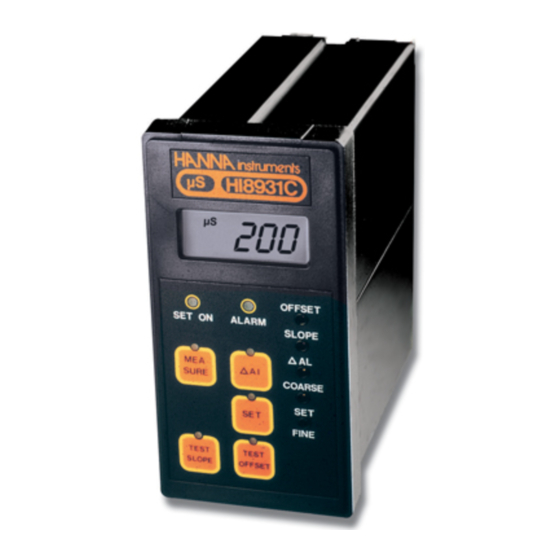
FUNCTIONAL DESCRIPTION H FUNCTIONAL DESCRIPTION H FUNCTIONAL DESCRIPTION HI I I I I 8931 8931 8931 8931 FUNCTIONAL DESCRIPTION H FUNCTIONAL DESCRIPTION H 8931 KEYPAD MEASURE To read measurements and enable diagnostic tests ΔALARM To display and set tolerance of the alarm To display and set the working dosing point TEST SLOPE Diagnostic function... - Page 6 REAR PANEL OF HI 8931 SERIES DIN connector for EC probe Trimmer for offset calibration Label with marked A, B, C or D instrument type SET terminals for connection to a dosing pump ALARM terminals for connection to an external alarm device...
- Page 7 MECHANICAL DIMENSIONS OF HI 8931 Front view of the panel-mounted unit These dimensions show the cutout size for the installation. Side view of the panel-mounted unit Adjustable location brackets (supplied with the meter) allow the indicator to slide into the cutout and will hold the unit securely in place. 190 mm (7.50") is the minimum amount of room required to install the indicator with the cables connected.
-
Page 8: Functional Description Hi 8936
FUNCTIONAL DESCRIPTION H FUNCTIONAL DESCRIPTION H FUNCTIONAL DESCRIPTION HI I I I I 8936 8936 8936 8936 FUNCTIONAL DESCRIPTION H FUNCTIONAL DESCRIPTION H 8936 HI 8936A HI 8936B HI 8936C HI 8936D HI 8936AL HI 8936BL HI 8936CL HI 8936DL 1. - Page 9 SIDE VIEW OF HI 8936 SERIES 1. Top cover 2. Cable glands for wiring MECHANICAL DIMENSIONS OF HI 8936A, HI8936B, HI 8936C, HI 8936D...
- Page 10 MECHANICAL DIMENSIONS OF HI 8936AL, HI8936BL, HI 8936CL, HI 8936DL...
-
Page 11: Conductivity Probes
CONDUCTIVITY PROBES CONDUCTIVITY PROBES CONDUCTIVITY PROBES CONDUCTIVITY PROBES CONDUCTIVITY PROBES HI 7635 In-line Conductivity Probe HI7635 is a one piece, molded conductivity probe with pipe threads (1" NPT) at both ends. This allows the probe to attach to an in-line system, and to be used in conjunction with the HI 8936 conductivity transmitter. - Page 12 HI7638 Tank Conductivity Probe HI 7638 conductivity probe combines the proven 4-ring potentiometric method of measuring conductivity with the platinum sensor and stain- less steel external thread. This method incorporates a series of four platinum rings into the probe shaft and is highly accurate requiring very little maintenance. The removable plastic cover resists the harmful effect of most chemicals and can be unscrewed for quick and simple maintenance.
-
Page 13: Specifications Hi 8931
SPECIFICATIONS H SPECIFICATIONS HI I I I I 8931 SPECIFICATIONS H 8931 8931 8931 SPECIFICATIONS H SPECIFICATIONS H 8931 Range 0.0 to 199.9 mS/cm HI 8931A 0.00 to 19.99 mS/cm HI 8931B 0 to 1999 µS/cm HI 8931C HI 8931D 0.0 to 199.9 µS/cm Resolution HI 8931A... -
Page 14: Specifications Hi 8936
Enclosure Black anodized aluminum body; front and back with ABS; transparent splash-proof front cover -10 to 50°C (14 to 122°F); RH 95% Environment 141 x 69 mm (5.6 x 2.7") Panel Cutout 1 kg (2.2 lb.) Weight SPECIFICATIONS H SPECIFICATIONS HI I I I I 8936 SPECIFICATIONS H 8936 8936... -
Page 15: Connections
CONNECTIONS CONNECTIONS CONNECTIONS CONNECTIONS CONNECTIONS REAR CONNECTIONS FOR HI 8931 • Power Connection Terminals 4-screw-terminal-strip for connection to a 3-wire power cable according to the indicated voltage (115 or 230V). • DIN connector socket For connection of the HI 7638 conductivity probe. - Page 16 • Set Select These contacts (4, 5) permit the activation of a Set Contact relay when the measured value is lower (connected terminals) or higher (open terminals) than the user's set value. See also page 25. • Recorder Output (terminals 1, 2, 3) These contacts are used for connection to a recorder output.
- Page 17 • Overtime dosing When enabled this feature ensures that overdosage is avoided. Select a desired maximum dosage period. If the dosage relay is active more than the selected period an alarm condition is ac- tivated and the dosage relay is deactivated. To set the overtime dosing period rotate the overtime knob to the proper position.
- Page 18 TERMINAL BOARD CONNECTIONS FOR H8936 • Remove the 4 screws and the top cover of the HI8936 conductivity trans- mitter to obtain access to the terminal board connections. • HI 8936 used in conjunction with HI 8931 controller Use a PVC insulated 4-core cable to connect the transmitter to the HI 8931 conductivity controller (see also page 22).
- Page 19 The 4-core cable has to be connected to the transmitter according to the la- bel instructions on the 4-terminal strip. The regulated D.C. supply required for the proper operation of the transmit- ter is "+20 V", labeled "+20 V" and "COM". The current (mA) out- put terminals are labeled "4-20 mA"...
- Page 20 CONDUCTIVITY PROBE CONNECTIONS The connections for HI 7635 are color coded for easy in- stallation and are as follows: HI 7635 cable HI 8936 transmitter Black or Grey Red or Pink SENSOR Brown or Orange probe pin 1 Blue probe pin 2 White probe pin 3 Green or Yellow...
-
Page 21: Operational Guide
OPERATIONAL GUIDE OPERATIONAL GUIDE OPERATIONAL GUIDE OPERATIONAL GUIDE OPERATIONAL GUIDE INITIAL PREPARATION & INSTALLATION Material needed: • a 3-wire power cable (to connec the HI 8931) • a PVC insulated 4-core cable (to connect the HI 8931 to HI8936) • rubber seals and a pipe sealant (for installation of HI 7635) INPUT FROM TRANSMITTER (HI8931 &... - Page 22 • The HI 8936 transmitter may be wall- mounted at any convenient location close to the measurement site. To minimize thermal drifts due to extreme temperature fluctuations, particularly for outdoors measurements, it is recom- mended to protect the transmitter inside a casing.
- Page 23 • It is recommended to install the HI 7635 vertically. This is to ensure that trapped air bubbles or turbulent flows cause minimal interfer- ence to the measurement system. The maximum working pressure of this unit is 5 bar (72.5 psi). WARNING: Do not use when temperature exceeds 80°C (176°F).
- Page 24 OPERATING INFORMATION All parameters are set through the front panel keys and trimmers. When any key is pressed, the corresponding LED lights up to indicate that the function is active. Make sure that the conductivity meter, transmitter and probe are cali- brated before taking measurements (see pages 28, 32 and 36 for cali- bration procedures).
- Page 25 Below Setpoint Control Operation Short the "SET SELECT" connectors “HI” and “LO” with a jumper wire. The set contact re- lay will close if the measured value is lower than the setpoint value, and the "SET ON" LED will light up. ALARM Press the "ΔALARM"...
- Page 26 The alarm contacts of HI 8931 remain closed during normal operation. If the measured conductivity level is not within the tolerance of the set value, the alarm contact will be open. TAKING MEASUREMENTS WITH HI 8931 After setting the working point and alarm value, press the "MEASURE" key.
- Page 27 If overtime dosing function is enabled overtime OFF terminals (1,2) open and the DOSING switch is in AUTO or ON position, an ALARM is generated if the dosing time exceeds the overtime set period (overtime knob on the rear panel). The dosing relay is not deactivated if the DOS- ING switch is in ON position but is deactivated if the switch is in AUTO position, when the...
-
Page 28: Calibration Procedure Of Hi 8931 & Hi 8936 With Hi 7635
CALIBRATION PROCEDURE OF CALIBRATION PROCEDURE OF CALIBRATION PROCEDURE OF CALIBRATION PROCEDURE OF CALIBRATION PROCEDURE OF HI 8931 & HI 8936 WITH HI 7635 HI 8931 & HI 8936 WITH HI 7635 HI 8931 & HI 8936 WITH HI 7635 HI 8931 & HI 8936 WITH HI 7635 HI 8931 &... - Page 29 • Ensure that the HI 7635 conductivity probe is dry. • When the power is on, the ammeter should read "4.0 mA". The HI 8936 transmitter with LCD should display "0". • If not, adjust the transmitter OFF- SET trimmer to read "4 mA" or "0" on the HI 8936 LCD.
- Page 30 • The reading will be converted to mA by the following formula: mA = K (measured value x 16/2000) + 4 K = conversion factor depending on the model Model Conversion factor K HI 8936 A/AL HI 8936 B/BL HI 8936 C/CL HI 8936 D/DL For example, using an HI 8936A, if the measured value is 123.4 mS, then...
- Page 31 • The calibration is now complete and the instrument is ready for use. All subsequent measurements will be compensated to 25°C (77°F). • If the instrument will not calibrate, refer to the "Probe Maintenance and Cleaning" section on page 46. •...
-
Page 32: Calibration Procedure Of Hi 8931 & Hi 8936 With Hi 7638
CALIBRATION PROCEDURE OF CALIBRATION PROCEDURE OF CALIBRATION PROCEDURE OF CALIBRATION PROCEDURE OF CALIBRATION PROCEDURE OF HI 8931 & HI 8936 WITH HI 7638 HI 8931 & HI 8936 WITH HI 7638 HI 8931 & HI 8936 WITH HI 7638 HI 8931 & HI 8936 WITH HI 7638 HI 8931 &... - Page 33 • Leave the HI 7638 conductivity probe in air (dry probe). • When the power is on, the ammeter should read "4.0 mA" or the HI 8936 transmitter with LCD should display "0". • If not, adjust the HI 8936 OFFSET trimmer to obtain "4 mA"...
- Page 34 • Pour at least 8 cm (3¼") of conductivity solution into a plastic beaker. • Immerse the probe into the conductivity solution. The holes on the sleeve must be completely submerged in the solution. • Tap the probe repeatedly on the bottom of the beaker and stir it to ensure that no air bubbles remain trapped inside the sleeve.
- Page 35 • FOR HI 8931 When the reading stabilizes, turn the SLOPE trimmer on the front of the HI 8931 until the LCD reading is the same as the calibration solution at 25°C (77°F), i.e. "80.0 mS" using HI 7034 with HI 8931A "12.88 mS"...
-
Page 36: Calibration Procedure Of Hi 8931 With Hi 7638
CALIBRATION PROCEDURE OF CALIBRATION PROCEDURE OF CALIBRATION PROCEDURE OF CALIBRATION PROCEDURE OF CALIBRATION PROCEDURE OF HI 8931 WITH HI 7638 HI 8931 WITH HI 7638 HI 8931 WITH HI 7638 HI 8931 WITH HI 7638 HI 8931 WITH HI 7638 Material needed •... - Page 37 • If the LCD does not show "0", adjust the OFFSET trimmer on rear panel. • Pour at least 8 cm (3¼") of conductivity solution into a plastic beaker. • Immerse the probe into the conductivity solution, while paying attention that the holes on the sleeve are completely sub- merged.
-
Page 38: Conductivity Versus Temperature Chart
CONDUCTIVITY VERSUS CONDUCTIVITY VERSUS CONDUCTIVITY VERSUS CONDUCTIVITY VERSUS CONDUCTIVITY VERSUS TEMPERATURE CHART TEMPERATURE CHART TEMPERATURE CHART TEMPERATURE CHART TEMPERATURE CHART °F HI7030 HI7031 HI 7033 HI 7034 HI7035 HI7039 °C (mS/cm) (mS/cm) (mS/cm) (mS/cm) (mS/cm) (mS/cm) 7150 48300 65400 2760 8220 53500 74100... -
Page 39: Diagnostic Tests
DIAGNOSTIC TESTS DIAGNOSTIC TESTS DIAGNOSTIC TESTS DIAGNOSTIC TESTS DIAGNOSTIC TESTS The HI 8931 controllers are designed with built-in diagnostic functions to enable the user to check and troubleshoot the instrument. The checks performed are through the front panel keys and can be used to isolate the cause of malfunction. - Page 40 Test Slope Press the "TEST SLOPE" key and the display should indicate the following values: HI 8931 100.0 mS ±35.0 mS HI 8931 10.00 mS ±3.50 mS HI 8931 1000 µS ±350 µS HI 8931 100.0 µS ±35.0 µS Note: The reading obtained by these functions will vary if the OFFSET and SLOPE trimmers on the front panel are adjusted.
-
Page 41: Installation Examples
INSTALLATION EXAMPLES INSTALLATION EXAMPLES INSTALLATION EXAMPLES INSTALLATION EXAMPLES INSTALLATION EXAMPLES Some typical installation setups are shown in the following examples: Example #1 Example #2 Example #3... - Page 42 Example #4 Example #5...
-
Page 43: Probe Maintenance And Cleaning
PROBE MAINTENANCE & CLEANING PROBE MAINTENANCE & CLEANING PROBE MAINTENANCE & CLEANING PROBE MAINTENANCE & CLEANING PROBE MAINTENANCE & CLEANING The probe can be compensated for normal contamination by a process of re-calibration. It is recommended to remove the probe from its installation regularly for maintenance. -
Page 44: Accessories
ACCESSORIES ACCESSORIES ACCESSORIES ACCESSORIES ACCESSORIES CONDUCTIVITY CALIBRATION SOLUTIONS HI 7030L 12880 µS/cm calibration solution, 500 mL HI 7030M 12880 µS/cm calibration solution, 230 mL HI 7031L 1413 µS/cm calibration solution, 500 mL HI 7031M 1413 µS/cm calibration solution, 230 mL HI 7033L 84 µS/cm calibration solution, 500 mL HI 7033M... - Page 45 CONDUCTIVITY PROBES HI 7635 In-line conductivity probe with 3 m (10') cable (for HI 8936 only) HI 7638 Conductivity probe for tank installation, with 3 m (10') cable (for HI 8936 or HI 943500)
-
Page 46: Warranty
If the repair is not covered by the warranty, you will be notified of the charges incurred. If the instrument is to be returned to HANNA instruments , first obtain a ®... - Page 47 Recommendations for Users Before using these products, make sure that they are entirely suitable for the environment in which they are used. Operation of these instruments in residential area could cause unacceptable interferences to radio and TV equipments, requiring the operator to take all necessary steps to correct interferences.
- Page 48 SALES & TECHNICAL SERVICE CONTACTS SALES & TECHNICAL SERVICE CONTACTS SALES & TECHNICAL SERVICE CONTACTS SALES & TECHNICAL SERVICE CONTACTS SALES & TECHNICAL SERVICE CONTACTS Australia: Tel. (03) 9769.0666 • Fax (03) 9769.0699 China: Tel. (10) 88570068 • Fax (10) 88570060 Egypt: Tel.
Need help?
Do you have a question about the HI 8931 Series and is the answer not in the manual?
Questions and answers