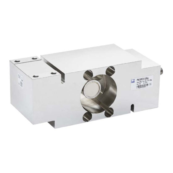
HBM PW29P Series Mounting Instructions
Load cell
Hide thumbs
Also See for PW29P Series:
- Mounting instructions (48 pages) ,
- Mounting instructions (64 pages)

Related Manuals for HBM PW29P Series


Summary of Contents for HBM PW29P Series
- Page 1 Mounting Instructions | Montageanleitung | Notice de montage English Deutsch Français PW29P...
- Page 2 Tel. +49 6151 803-0 Fax +49 6151 803-9100 info@hbm.com www.hbm.com Mat.: 7-0101.0008 DVS: A03578_02_Y00_00 HBM: public 09.2018 E Hottinger Baldwin Messtechnik GmbH. Subject to modifications. All product descriptions are for general information only. They are not to be understood as a guarantee of quality or durability.
- Page 3 Mounting Instructions | Montageanleitung | Notice de montage English Deutsch Français PW29P...
-
Page 4: Table Of Contents
..........PW29P A03578_02_Y00_00 HBM: public... -
Page 5: Safety Instructions
S Breaking loads S Temperature limits S Limits of electrical loading capacity Note, that when several load cells are installed in a scale, there is not always an even distribution of load on the individual load cells. PW29P A03578_02_Y00_00 HBM: public... - Page 6 Load cells can break, particularly in the case of overloading. The breakage of a load cell can also cause damage to property or injury to persons in the vicinity of the load cell. PW29P A03578_02_Y00_00 HBM: public...
- Page 7 If you need more information about disposal, please contact your local authorities or the dealer from whom you purchased the product. PW29P A03578_02_Y00_00 HBM: public...
- Page 8 3. As system startup engineers or service engineers, you have successfully completed the training to qualify you to repair the automation systems. You are also authorized to ground and label circuits and equipment and place them in operation in accordance with safety engineering standards. PW29P A03578_02_Y00_00 HBM: public...
-
Page 9: Markings Used
This marking draws your attention to information about the product or about handling the product. Information Emphasis Italics are used to emphasize and highlight text and See…. references to other chapters and external documents. PW29P A03578_02_Y00_00 HBM: public... -
Page 10: Symbols On The Product
Symbols on the product CE mark The CE mark enables the manufacturer to guarantee that the product complies with the requirements of the rele vant EC directives (the declaration of conformity is avail able at http://www.hbm.com/HBMdoc). PW29P A03578_02_Y00_00 HBM: public... -
Page 11: Conditions On Site
Deposits Dust, dirt and other foreign matter must not be allowed to accumulate sufficiently to divert some of the measuring force onto the housing, thus invalidating the measured value (force shunt). PW29P A03578_02_Y00_00 HBM: public... -
Page 12: Mechanical Installation
S Welding currents must not be allowed to flow over the transducer. If there is a risk that this might happen, you must provide a suitable low‐ohm connection to electrically bypass the transducer. HBM provides the highly flexible EEK ground cable for this purpose, for example, that is screwed on above and below the transducer. - Page 13 Load must not be applied to the side where the cable connection is located, as this would cause a force shunt. Setting the overload stop Type PW29P load cells are fitted with an adjustable overload stop. Set this overload stop before starting up the load cell. PW29P A03578_02_Y00_00 HBM: public...
- Page 14 “Limit load at max. 100 mm eccentricity" specification, and take into consideration the moment produced by the eccentricity in your individual application. Then adjust the screw of the overload stop and fix it in position with a screw locking adhesive, such as Loctite. PW29P A03578_02_Y00_00 HBM: public...
-
Page 15: Electrical Connection
With this connector pin assignment, the output voltage at the measuring amplifier is positive when the transducer is loaded (see Fig. 4.1). The pin assignment for the cables available as accessories can be found in Section 8 on page 18. PW29P A03578_02_Y00_00 HBM: public... -
Page 16: Connection In A Four-Wire Configuration
Extension cable Only use shielded, low‐capacitance measurement cables for extending. Ensure that connection is perfect, with a low contact resistance. The cable of a six‐wire transducer can be extended with a cable of the same type. PW29P A03578_02_Y00_00 HBM: public... -
Page 17: Emc Protection
EMC protection for the measuring chain. Electrical and magnetic fields often induce interference voltages in the measuring circuit. Therefore: S Use shielded, low‐capacitance measurement cables only (HBM cables fulfill both conditions). S Do not route the measurement cables parallel to power lines and control circuits. -
Page 18: Specifications
Specifications Specifications Information Further product information can be found at www.hbm.com/pw. PW29P A03578_02_Y00_00 HBM: public... -
Page 19: Dimensions
8 x M8 (M12 1-KAB168/ 1-KAB175 M12x1.75 11.5 95.5 Connector plug 15.5 25.5 M12 for maximum capacities 500 kg to 1000 kg 1-KAB168: ØD = 14.5; L = 62 1-KAB175: ØD = 16; L = 62 PW29P A03578_02_Y00_00 HBM: public... -
Page 20: Accessories
Pin assignment 1-KAB168 Color code Connection White Measurement signal (+) Measurement signal (-) Blue Excitation voltage (+) Pink Excitation voltage (-) Green Sense lead (+) Gray Sense lead (-) Yellow Not in use Brown Not in use PW29P A03578_02_Y00_00 HBM: public... - Page 21 Accessories Pin assignment 1-KAB175 Color code Connection White Measurement signal (+) Measurement signal (-) Blue Excitation voltage (+) Black Excitation voltage (-) Green Sense lead (+) Gray Sense lead (-) PW29P A03578_02_Y00_00 HBM: public...
Need help?
Do you have a question about the PW29P Series and is the answer not in the manual?
Questions and answers