Emerson Rosemount 700XA Reference Manual
Gas chromatograph
Hide thumbs
Also See for Rosemount 700XA:
- Install (12 pages) ,
- Reference manual (294 pages) ,
- Quick start manual (80 pages)
Advertisement
Quick Links
Advertisement

Related Manuals for Emerson Rosemount 700XA


Summary of Contents for Emerson Rosemount 700XA
- Page 1 Reference Manual 2-3-9000-744, Rev H July 2020 ™ Rosemount 700XA Gas Chromatograph...
-
Page 2: Table Of Contents
July 2020 Overview This section provides a description of the Rosemount 700XA system, an explanation of the theory of operation, and a glossary of chromatograph terminology. Contents Overview......................................2 Equipment description and specifications............................21 Getting started....................................32 Installation and start-up ..................................35 Operation and maintenance................................ - Page 3 Time, in seconds, that elapses between the start of analysis and the sensing of the maximum concentration of each component by the detector. Ring indicator. RLSD Received line signal detect. A digital simulation of a carrier detect. Request to send. Rosemount 700XA...
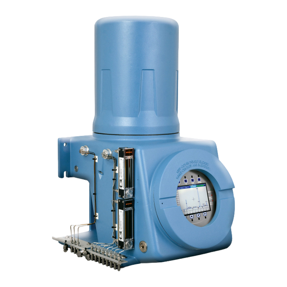
- Page 4 Transmit data, or signal out. System description The Rosemount 700XA is a high-speed gas chromatograph (GC) system that is engineered to meet specific field application requirements based on typical hydrocarbon stream composition and anticipated concentration of selected components. In its standard configuration, the analyzer can handle up to eight streams: seven sample streams and one calibration stream.
- Page 5 Failure to follow this warning may result in injury or death to personnel. Do not use a personal computer (PC) or printer in a hazardous area. Emerson provides serial and Ethernet communication links to connect the analyzer to the PC and to connect to other computers and printers in a safe area.
- Page 6 Embedded GC firmware The GC’s embedded firmware supervises operation of the Rosemount 700XA through its internal microprocessor-based controller. All direct hardware interface is via this control software. It consists of a multi-tasking program that controls separate tasks in system operation, as well as hardware self-testing, user application downloading, startup, and communications.
- Page 7 July 2020 MON2020 MON2020 provides operator control of the Rosemount 700XA, monitors analysis results, and inspects and edits various parameters that affect the analyzer operation. It also controls display and printout of the chromatograms and reports, and it stops and starts automatic analysis cycling or calibration runs.
- Page 8 Figure 2: Analyzer Assembly with TCD Bridge A. Detector block (in heated upper section of analyzer) B. Reference flow (carrier gas) C. Measurement flow ("MV") D. Signal out E. Preamplifier (in analyzer electronics housing) F. Detector bridge G. DC power H. Valves, columns, etc. Emerson.com/Rosemount...
- Page 9 Flame ionization detector (FID) Another detector available for the Rosemount 700XA is the flame ionization detector (FID). The FID requires a polarization voltage, and its output is connected to the input to a high impedance amplifier that is called an electrometer.
- Page 10 The Emerson µFPD solution consists of three key parts: burner, fiber cable, and PMT electronics. The hydrogen and air in the burner help to burn the sample containing sulfur components. The light emitted from the chemical reaction is then transmitted using the fiber cable from the oven assembly to the electronics module.
- Page 11 July 2020 Figure 5: µFPD Detector - Front View A. µFPD burner Rosemount 700XA...
- Page 12 July 2020 Figure 6: µFPD Burner - Back View A. µFPD burner B. Fiber cable Emerson.com/Rosemount...
- Page 13 July 2020 Figure 7: µFPD Burner - Side View A. µFPD burner and cable Rosemount 700XA...
- Page 14 You can select the number of ignition attempts on the Hardware → Detector screen. If the electrometer does not succeed in igniting, then the GC shuts off the hydrogen, triggers an alarm, and waits for attention from the operator. Related information Micro flame photometric detector (µFPD) Emerson.com/Rosemount...
- Page 15 The external chamber is a thermo electric cooler (TEC) controlled chamber, which houses the interal chamber along with the electronic board that generates high voltage power through the PMT. Figure 9: Electronics Module, Exploded View A. Apply thermal compound to both sides. Rosemount 700XA...
- Page 16 On the outside of the external chamber is the electronics main board. This board is the vital part of the µFPD electronics module. It controls the temperature of the TEC, provides power to the igniter, monitors the flame temperature, and digitizes the PMT signal and transmits to the main central processing unit (CPU) using CAN bus. Emerson.com/Rosemount...
- Page 17 Integrate Inhibit is turned off. Analysis is started in a region of signal quiescence and stability, such that the signal level and activity can be considered as baseline values. Rosemount 700XA...
- Page 18 (with a calibration gas mixture that has known concentrations). The response factor calculation, using the external standard, is: where Area response factor for component n in area per mole percent Emerson.com/Rosemount...
- Page 19 Number of calibration runs used to calculate the response factors The percent deviation of new RF averages from old RF average is calculated in the following manner: where the absolute value of percent deviation has been previously entered by the operator. Rosemount 700XA...
- Page 20 Non-normalized concentration of component n in mole percent for each k component CONC Non-normalized concentration of component n in mole percent Number of components to be included in the normalization Note The average concentration of each component will also be calculated when data averaging is requested. Emerson.com/Rosemount...
-
Page 21: Equipment Description And Specifications
Equipment description and specifications Equipment description The Rosemount 700XA consists of a copper-free aluminum explosion-proof chamber and a front panel assembly. The chamber is divided into two compartments that together house the gas chromatograph's (GC's) major components. This GC is designed for hazardous locations. - Page 22 There are two types of switch panels: 8-stream and 18-stream. The 8-stream switch panel is the standard panel, and is used when the GC has only one heater/solenoid board installed; if two heater/solenoid boards are installed, then the 18-stream switch panel is used. Emerson.com/Rosemount...
- Page 23 CPU - Green light blinks continuously while the GC is running. ■ Valves - Turns green if the valves are functioning automatically; turns red if the valves’ automatic settings have been overridden. Note During GC start up, all LEDs turn on for approximately ten seconds. Rosemount 700XA...
- Page 24 ■ Adjustable auto-backlighting ■ 8 infrared-activated touch screen keys that eliminate the requirement for a magnetic pen ■ Complete GC status, control, and diagnostics, including full chromatogram display Local operator interface (LOI) for more information about operating the LOI. Emerson.com/Rosemount...
- Page 25 Methanator undetectable carbon dioxide and/or carbon monoxide into methane by adding hydrogen and heat to the sample. Liquid sample injection The optional LSIV can vaporize a liquid sample, thereby expanding the GC’s capability to measure valve (LSIV) liquids. Rosemount 700XA...
- Page 26 Applying 110/220 Vac to a DC power input unit severely damages the unit. Failure to check the power supply label may result in injury or death to personnel or cause damage to the equipment. Note The Rosemount 700XA CSA-certified unit is equipped with 3/4-inch NPT-thread adapters. Emerson.com/Rosemount...
- Page 27 The mechanical pressure regulators and gauges are used to set and monitor the pressure of the carrier gas flow through the GC's columns, as well as the pressure of the FID/FPD air and fuel (H ), if installed. The regulators and gauges are typically located on front of the analyzer below the electronics enclosure. Figure 20: Regulators and Gauges Rosemount 700XA...
- Page 28 Basic system; no alternative options included Liquid sample injection valve (LSIV) option included Heat trace option with a maximum 176 ° F (80 ⁰C) temperature switch setpoint Heat trace option with a maximum 230 °F (110 ⁰C) temperature switch setpoint Emerson.com/Rosemount...
- Page 29 — 3 in. (89.0 mm) — 4 in. (114.3 mm) ■ Direct wall mount ■ Standard: 24 Vdc (21-30 Vdc operating voltage range); maximum 150 watts Power ■ Optional: 100-120/240 Vac; 50-60 Hz Note Voltage range includes line voltage variations. Rosemount 700XA...
- Page 30 ■ Eight digital inputs (isolated) card ■ Five digital outputs (isolated) card ■ One RS-232, RS-422, or RS-485 serial connection card (up to two maximum) Ethernet Two available connections ■ one RJ45 port ■ one four-wire termination – with 10/100 Mbps Emerson.com/Rosemount...
- Page 31 86,464 (240 days with 4-minute cycle time) Final calibration results Calibration results 100 (per row in Analysis Configuration table) Final validation results 370 (per row in Analysis Configuration table) Validation results 100 (per row in Analysis Configuration table) Rosemount 700XA...
-
Page 32: Getting Started
Failure to follow this warning may result in injury or death to personnel. Do not use a personal computer (PC) or printer in a hazardous area. Emerson provides serial and Ethernet communication links to connect the analyzer to the PC and to connect to other computers and printers in a safe area. - Page 33 Unpack and inspect the Rosemount 700XA gas chromatograph upon receipt. WARNING LIFTING HAZARD The Rosemount 700XA is heavy equipment. Failure to observe this warning may cause serious injury to personnel. Use two people to move the GC. Observe all proper lifting methods as defined by your site operating procedures.
- Page 34 Do not use a personal computer (PC) or printer in a hazardous area. ® Emerson provides serial port and Modbus communciation links to connect the gas chromatograph (GC) to the PC and to connect to other computers and printers in a safe area.
-
Page 35: Installation And Start-Up
Note Because the Rosemount 700XA is available in different configurations, it is possible that not all of the instructions in this section apply to your particular gas chromatograph (GC). In most cases, however, to install and set up a Rosemount 700XA, Emerson recommends that you follow the instructions in the same order as they are presented in this manual. - Page 36 Due to the size, weight, and shape of the gas chromatograph (GC), at least two people are required to safely mount it. Ensure that you understand the installation procedur before handling the GC and collect the appropriate tools beforehand. When putting the GC into its final position, be careful to avoid damaging any of the external components or their attachments. Emerson.com/Rosemount...
- Page 37 The simplest mounting arrangement is the wall mount. If you specify Wall Mount on the sales order, Emerson will ship the gas chromatograph (GC) with a wall mount installation kit. Four locations on the mounting ears are available for support.
- Page 38 6. Orient the GC so that the notches in the mounting ears can be placed over the lower bolts on the plate and then add the washers and nuts. 7. Place the nuts with washers on the upper bolts and then tighten all bolts. 8. Adjust the lower bracket to align the bolts with the plate. Tighten the bolts. Emerson.com/Rosemount...
- Page 39 Floor mount If you specify Floor Mount in the sales order, Emerson sends the arrangement pre-assembled with the gas chromatograph (GC). The arrangement includes an additional support stand that is intended to be anchored to a floor or an instrument pad. The base rails have holes that are 13.625 in.
- Page 40 If you don't follow this precaution, the data and control signals to and from the GC could be adversely affected. Do not place any loop of extra cable left for service purposes inside the GC purged housing near the conduit entry for AC power. Emerson.com/Rosemount...
- Page 41 Failure to observe precautionary signs may result in serious injury or death to personnel. Observe all precautionary signs posted on the certified explosion-proof equipment. Consult your company's polices and procedures and other applicable documents to determine wiring and installation practices that are appropriate for hazardous areas. Rosemount 700XA...
- Page 42 ■ Install a block valve downstream of sample takeoff point for maintenance and Valving shutdown. ■ The block valve should be a needle valve or cock valve type, of proper material and packing, and rated for process line pressure. Emerson.com/Rosemount...
- Page 43 July 2020 Electrical installation NOTICE Emerson switches off central processing unit (CPU) boards before shipping to preserve their batteries. Before installing the CPU board, be sure to switch it on.. Figure 24: CPU Board A. SW7 battery power ON Connect power supply...
- Page 44 2. Bring the two leads in through one of the two possible entries on the lower compartment. Connect to the termination plug provided with the GC. Figure 26: Wiring Entries on the Under Side of the Lower Enclosure Attribute Wire Color + (positive) Emerson.com/Rosemount...
- Page 45 If the red (+) and black (-) leads are inadvertently reversed, no damage will occur; however, the system will not have power. 3. Connect the DC power leads to the power disconnect switch that should be properly fused. The recommended fuse size is 8 amps. Rosemount 700XA...
- Page 46 2. Bring the power leads in through the left entry on the bottom of the enclosure. 3. If necessary at remote locations, connect the GC chassis ground wire to an external copper ground rod. Grounding precautions regarding electrical and signal grounding. Connect gas lines Emerson.com/Rosemount...
- Page 47 Communication protocol Maximum distance RS-232 50 ft. (15.24 m) RS-422/RS-485 4,000 ft. (1,219.2 m) Ethernet (CAT5) 300 ft. (91.44 m) Rosemount 700XA...
- Page 48 Connect to the gas chromatograph (GC) using MON2020 To connect to the GC using the RJ45 Ethernet1 connection, do the following: Procedure 1. Start MON2020. The Connect to GC window displays. 2. Locate the default Direct-DHCP under the GC Name column. Emerson.com/Rosemount...
- Page 49 This GC directory is created automatically when MON2020 is installed. You can rename the GC, but do not change the IP address that it references, 192.168.135.100. 3. Click the associated Ethernet button. MON2020 prompts you to enter a user name and password. 4. Enter your user name and password. 5. MON2020 connects you to the GC. Rosemount 700XA...
- Page 50 4. Do the following to ensure that your network adapter is enabled: a) Go to Start → Control Panel → Network Connections..b) Check the status of the Local Area Connection icon. If the status appears as Disabled, right-click the icon and select Enable from the context menu. Emerson.com/Rosemount...
- Page 51 The Install from Disk dialog window appears. e) Click Browse The Browse dialog window displays. f) Navigate to the MON2020 install directory (typically C:\Program Files (x86)\Emerson Process Management\MON2020) and select Daniel Direct Connection.inf. g) Click Open. You return to the Install from Disk dialog window.
- Page 52 The Rosemount 700XA has a wired Ethernet terminal at TB11 on the backplane that you can connect to with a static IP address. All that is needed is a PC, typically a notebook computer, and a two-wire, twisted pair, CAT5 Ethernet cable with one of its plugs removed to expose the wires.
- Page 53 The Ethernet port at TB11: Enter the appropriate values in the Ethernet2 IP Address, the Ethernet 2 Subnet, and the Default Gateway fields. b) The RJ45 Ethernet port at J22: Enter the appropriate values in the Ethernet1 IP Address, the Ethernet1 Subnet, and the Default Gateway fields. Rosemount 700XA...
- Page 54 MON2020 adds a new GC profile to the end of the table. Note You can name the GC’s profile as well as add a short description. c) Select the new profile and click Ethernet... Enter the GC’s static IP address in the IP address field. d) Click OK. Emerson.com/Rosemount...
- Page 55 4. Route digital in/out (I/O) lines away from the sensitive detector lines (on the left side of the backplane) and away from the analog inputs and outputs. There are connections for five digital inputs on the backplane at TB7, as indicated in the following table. Rosemount 700XA...
- Page 56 Failure to follow this precaution may cause a short circuit and damage equipment. Allow only a minimum exposure of bare wires to prevent short circuits. 2. Insert the exposed end into the clamp beneath the termination screw. 3. Tighten the screw. Emerson.com/Rosemount...
- Page 57 Figure 34: Typical Wiring Table 4: ROC800 Discrete digital wiring Terminal Label Definition CH 1 Positive CH 2 Positive CH 3 Positive CH 4 Positive CH 5 Positive CH 6 Positive CH 7 Positive CH 8 Positive Common Common Rosemount 700XA...
- Page 58 The discrete outputs are located on TB3, which is a 15-pin connector, and have five Form-C relays on the back plane. All contact outputs have a rating of 1A at 30 Vdc. Refer to drawing BE-22175 in List of engineering drawings - Rosemount 700XA Figure 35: TB3 on the Backplane Table 5 lists the discrete digital output function for each pin on the TB3 connector.
- Page 59 Optional discrete digital inputs (DI) When plugged into one of the optional card slots in the card cage, the Emerson ROC800 DI card provides eight additional discrete digital inputs. The discrete digital inputs can monitor the status of relays, open-collector or open-drain type solid-state switches, and other two-state devices.
- Page 60 1. Expose the end of the wire to a maximum length of ¼ in. (6.4 mm). Note Twisted-pair cables are recommended for I/O signal wiring. The module’s terminal blocks accept wire sizes between 12 and 22 American wire gauge (AWG). Allow some slack when making connections to prevent strain. Emerson.com/Rosemount...
- Page 61 2. Insert the exposed end into the clamp beneath the termination screw. 3. Tighten the screw. Wiring the analog inputs All Rosemount 700XA gas chromatographs (GCs) have at least two analog inputs. An additional four analog inputs are available with a ROC800 AI-16 card (see Wire a ROC800 digital output (DO) module) that can be installed into one of the optional slots in the card cage.
- Page 62 3. Click Save to save the changes and keep the window open, or click OK to save the changes and close the window. Typical wiring for line-powered transmitters The following drawing shows the most common wiring plan for supplying power to two 4-20 mA transmitters, such as pressure sensor transmitters. Emerson.com/Rosemount...
- Page 63 AI module’s analog signal can be calibrated to zero. For more information, see Analog Input Modules (ROC800-Series at Emerson's ROC800-Series website. Wire an ROC800 AI-16 module CAUTION ELECTROSTATIC DISCHARGE (ESD) Operators and technicians must wear an electrostatic wrist strap when handling printed circuit cards to prevent shorting the boards through static electricity. Rosemount 700XA...
- Page 64 To put an analog input’s resistor in circuit, flip the appropriate dip switch to I; to put an analog input’s resistor out of circuit, flip the appropriate dip switch to V. Calibrate a ROC800 AI-16 module Prerequisites ™ To calibrate the ROC800 AI-16 module you must have a personal computer (PC) with the ROCLINK 800 Configuration software installed and open. Emerson.com/Rosemount...
- Page 65 Step Analog output wiring The Rosemount 700XA has at least six analog outputs. An additional four analog inputs are available with an ROC800 AO card that can be installed into one of the optional slots in the card cage. Rosemount 700XA...
- Page 66 It is possible to furnish power to each analog output while maintaining isolation between channels. Consult Figure 42 before wiring a customer-powered device: Procedure 1. Use Figure 42 to provide power wiring to each analog output while maintaining isolation between channels. Emerson.com/Rosemount...
- Page 67 1. Expose the end of the wire to a maximum length of ¼ in. (6.4 mm). Note Emerson recommends using twisted-pair cables for in/out (I/O) signal wiring. The module’s terminal blocks accept wire sizes between 12 and 22 American wire gauge (AWG). Expose minimal bare wire to prevent short circuits. Allow some slack when making connections to prevent strain.
- Page 68 If all the component peaks are identified, the GC computes the calibration gas' energy value and performs the EV Check. ■ After a successful calibration, the GC computes the gas' energy value with the new response factors and performs the EV Check Emerson.com/Rosemount...
- Page 69 Note Refer to the analyzer's drawing documentation package that shipped with the GC for leak checking and identifying vents. Emerson tested the GC and fittings for leaks at the factory prior to shipment. Procedure 1. Plug the measure vent (labeled MV) vent line if it is open.
- Page 70 The temperature values for the heaters should indicate that the GC is warming up. The Status column displays OK. 8. Select Control → Auto Sequence..For more information about this function, refer to the MON2020 Software for Gas Chromatographs Reference Manual. Emerson.com/Rosemount...
- Page 71 Unless stated otherwise in the product documentation, ensure that the pressure of the calibration and sample line is regulated at 10 to 30 psig (68.9 to 206.8 kPa). 15 psig (103.4 kPa) is recommended. c) Validate calibration gas and retention times and run a manual calibration. Rosemount 700XA...
-
Page 72: Operation And Maintenance
Operation and maintenance Warning and precautions WARNING Failure to observe the precautionary signs posted on the Rosemount 700XA can result in injury or death to personnel or cause damage to the equipment. Observe all precautionary signs posted on the GC. - Page 73 10. Run a normal calibration on the stream associated with the HCG. The GC is ready to analyze the sample or validation stream using the 2 Pt Exp with the response factor that was calculated during the LCG and HCG runs. Rosemount 700XA...
- Page 74 Also, create a diagnostic file, which contains calibration and analysis chromatograms, alarm and event logs, analysis reports, and the complete configuration file, and file it with the checklist, furnishing a positive dated record of the Rosemount 700XA. You can compare these chromatograms and reports to the chromatograms and reports run during the troubleshooting process.
- Page 75 July 2020 Figure 44: Sample Maintenance Checklist Rosemount 700XA...
- Page 76 Keep electrical components and assemblies in their protective (conductive) carriers or wrapping until ready for use. Use the protective carrier as a glove when installing or removing printed circuit assemblies. Wear an electrostatic discharge (ESD) strap to prevent static discharge when installing or removing printed circuit assemblies. Emerson.com/Rosemount...
- Page 77 July 2020 Figure 45: SW7 on the Central Processing Unit (CPU) Board A. SW7 switch (ON is towards the dot.) Rosemount 700XA...
- Page 78 1. Save the gas chromatograph (GC) configuration file. In MON2020, go to File → Save Configuration (to PC). 2. Power down the GC. 3. Open the GC cover. 4. Remove the clear plastic cover that holds the boards in place. 5. Remove the CPU board. Emerson.com/Rosemount...
- Page 79 C. Turn SW4 OFF (away from the dot). D. Turn SW6 OFF (away from the dot). Note Rosemount 700XA GCs are tagged with CPU board part number 7A00555G02. 7. Install the new CPU board in the card cage. Rosemount 700XA...
- Page 80 4. Remove the CPU board from the card cage. 5. Ensure the switches on the CPU board are as shown in Figure 6. Set the CPU board aside for ten minutes to bleed the contents of the battery backed random access memory (RAM). Emerson.com/Rosemount...
- Page 81 Required tools for valve maintenance The tools required for performing repair and general maintenance on the Rosemount XA Series valve assemblies are: ■ Torque wrench, scaled in foot-pounds ■ ½-in. socket for 10-port valves ■ 7/16-in. socket for 6-port valves Rosemount 700XA...
- Page 82 Overhaul a valve Note Rosemount valves have a lifetime warranty. Replacement factory-built XA Series valves are available. Call your local Emerson Customer Care representative for more information. If you are overhauling a 6-port valve, refer to drawing #CE-22260; If you are overhauling a 10-port valve, refer to drawing #CE-22300.
- Page 83 Procedure 1. Remove the thermal cover from the upper enclosure. 2. Loosen the ultem thumb screw and tilt the oven on its side to gain access to the solenoids that are located on the underside of the ultem. Rosemount 700XA...
- Page 84 A flat-head screwdriver is required for removing and replacing TCDs. Use a multimeter to test the thermistor pair. Thermal conductivity detector (TCD) replacement parts Consult the parameter list that was provided with the gas chromatograph (GC) for the thermistor kit required to replace one TCD. A new thermistor seal (2-6-5000-084) is also required. Emerson.com/Rosemount...
- Page 85 EXPLOSION HAZARD Failure to de-energize the analyzer may cause an explosion and severely injure personnel. Do not open the enclosure unless the area is known to be non-hazardous or unless all devices within the enclosure have been de-energized. Rosemount 700XA...
- Page 86 6. The TCD thermistors are held within the TCD block by the retainer nut. To replace the thermistor, do the following: a) Unscrew and release the thermistor leads from the termination block. b) Unscrew the retainer nut from the TCD block. Emerson.com/Rosemount...
- Page 87 FID. WARNING EXPLOSION HAZARD Failure to de-energize the analyzer may cause serious injury or death to personnel. Do not open when energized or when an explosive atmosphere may be present. Keep cover tight while circuits are live. Rosemount 700XA...
- Page 88 Use a backing wrench on the bolt fronting the FID cap when removing the vent connector. 6. Remove the screw from the top of the FID assembly. CAUTION ELECTROSTATIC DISCHARGE (ESD) Operators and technicians must wear an electrostatic wrist strap when handling printed circuit cards to prevent shorting the boards through static electricity. Emerson.com/Rosemount...
- Page 89 4. Tighten the tubing nut connector, securing the FID exhaust tube. 5. Screw in the tubing nut connectors located at the base of the FID. 6. Install the explosion-proof cover over the FID assembly and secure to the base with eight bolts. Rosemount 700XA...
- Page 90 July 2020 Replace igniter/thermocouple assembly Figure 54: Igniter/Thermocouple Assembly Front View A. Bulkhead nut B. Screws and washers C. Fitting D. Bulkhead nut E. Igniter/thermocouple assembly F. Igniter connector Emerson.com/Rosemount...
- Page 91 8. Rotate the µFPD burner back to its original position. Finger tighten the screws and washers (B). 9. Tighten the bulkhead nut (Figure 54, A) to 20-in. lb. 10. Secure the screws and washers (B). 11. Reconnect the ignitor connector (Figure 54, C). Rosemount 700XA...
- Page 92 ■ Resistances measured between pins 3 and 4 shall be less than 4 ohms. Recommended actions 1. Detach connectors. Voltage between pins 1 and 2 on extension cable end shall measure 3.0 to 3.3 Vdc while igniting. You can manually ignite with the Detectors pop-up window. Emerson.com/Rosemount...
- Page 93 ■ 7 ⁄64-in. Allen wrench ■ Phillips screwdriver ■ Flathead screwdriver Procedure 1. Disconnect all power to the unit. Allow at least 10 minutes for the components to cool-down. 2. Remove the explosion-proof dome and the thermal hood. Rosemount 700XA...
- Page 94 3. Use a 7⁄64-in. Allen wrench and remove the fiber cable screws from the µFPD burner mounting plate to disconnect the cable. Figure 58: µFPD Burner Disassembly Back View A. µFPD burner B. µFPD fiber cable clamp C. Screws µFPD burner D. µFPD fiber cable E. Thumb screw Emerson.com/Rosemount...
- Page 95 July 2020 4. Affix electrical tape to the end of the disconnected fiber cable to prevent debris or moisture contamination. Figure 59: µFPD Fiber Cable Disassembled 5. Remove the two screws from the µFPD burner housing. Rosemount 700XA...
- Page 96 July 2020 6. Remove the fiber cable clamp screws and O-ring. Set aside for reassembly. Figure 60: µFPD Fiber Cable Clamp Dissassembly Emerson.com/Rosemount...
- Page 97 July 2020 7. Disconnect the air intake, helium intake, and sample lines. Figure 61: µFPD Ignitor and Intake Lines A. Igniter/thermocouple (TC) B. Air intake port C. Helium intake port D. Sample intake port Rosemount 700XA...
- Page 98 July 2020 8. Loosen the top bulkhead nut and remove the µFPD burner assembly. Figure 62: µFPD Burner Bulkhead A. Bulkhead nut Emerson.com/Rosemount...
- Page 99 ■ 7 ⁄64-in. Allen wrench ■ Phillips screwdriver ■ Flathead screwdriver Procedure 1. Disconnect all power to the unit. Allow at least 10 minutes for the components to cool-down. 2. Remove the explosion-proof dome and the thermal hood. Rosemount 700XA...
- Page 100 3. Attach the male fitting of the µFPD burner to the bulkhead nut on the GC. Finger tighten the bulkhead nut. Figure 63: µFPD Burner Installation A. µFPD burner 4. Attach and finger tighten two screws/washers on the plastic bracket to center post. Emerson.com/Rosemount...
- Page 101 July 2020 5. Tighen the bulkhead connector with torque of 20 in. lb. Figure 64: µFPD Fiber Cable Clamp Assembly 6. Install the fiber cable to the µFPD burner connector and secure with cable clamp. Rosemount 700XA...
- Page 102 July 2020 7. Install the two screws in the rear of the µFPD burner housing. Figure 65: µFPD Burner Assembly A. µFPD burner B. µFPD cable clamp C. Screws µFPD burner D. µFPD fiber cable E. Thumb screw Emerson.com/Rosemount...
- Page 103 Internal components may be hot. Failure to allow the GC to cool down may result in injury to personnel. Allow the GC to cool down before disassembling any components. Always wear proper personal protective equipment (PPE) when disassembling the analyzer. Rosemount 700XA...
- Page 104 July 2020 Figure 66: µFPD Ignitor and Intake Lines A. Igniter/TC B. Air intake port C. Helium intake port Emerson.com/Rosemount...
- Page 105 ■ 7 ⁄64-in. Allen wrench ■ Phillips screwdriver ■ Flathead screwdriver Procedure 1. Disconnect all power to the unit. Allow at least 10 minutes for the components to cool-down. 2. Remove the explosion-proof dome and the thermal hood. Rosemount 700XA...
- Page 106 3. Use a 7⁄64-in. Allen wrench and loosen the fiber cable screws from the µFPD burner mounting plate to disconnect the cable. Figure 67: µFPD Burner Disassembly A. µFPD burner B. Fiber cable clamp C. Screws µFPD burner D. µFPD fiber cable E. Thumb screw Emerson.com/Rosemount...
- Page 107 4. Affix electrical tape to the end of the disconnected fiber cable to prevent debris or moisture contamination. Figure 68: µFPD Fiber Cable Disassembled 5. Loosen the screws holding the fiber cable bottom clamp. Slide the bottom clamp up. Figure 69: µFPD Fiber Cable Clamp Dissassembly Rosemount 700XA...
- Page 108 July 2020 6. Loosen the thumb screw and carefully lift and tilt the Ultem plate and upper assembly. Emerson.com/Rosemount...
- Page 109 July 2020 Figure 70: Upper Assembly Tilted Rosemount 700XA...
- Page 110 July 2020 7. Loosen the fiber cable clamp screws and disconnect the fiber cable from the PMT. Figure 71: Fiber Cable Disconnected from the µFPD PMT Module A. Fiber cable B. Cable clamp C. Cable clamp screws Emerson.com/Rosemount...
- Page 111 2. Use a large flathead screwdriver to tighten the two µFPD PMT module bracket screws. 3. Use a Phillips head screwdriver and tighten the two screws to attach the stream solenoid manifold. 4. Attach the J6, J10, and J2 wire terminals to the µFPD PMT module. Rosemount 700XA...
- Page 112 July 2020 Figure 73: µFPD PMT Module Connections A. J6 - CAN and power signals B. J10 - igniter C. J2 - thermocouple D. USB connector E. PMT module bracket screws F. Stream manifold screws G. Stream manifold Emerson.com/Rosemount...
- Page 113 The shoulder of fiber cable shall be flush with clamp surface to ensure fiber cable is fully inserted into PMT module. Figure 74: Fiber Cable Connected to the µFPD PMT Module A. Fiber cable B. Cable clamp C. Cable clamp screws Rosemount 700XA...
- Page 114 July 2020 6. Carefully tilt and lower the Ultem plate and upper assembly. Tighten the thumb screw. Emerson.com/Rosemount...
- Page 115 July 2020 Figure 75: Upper Assembly Tilted Rosemount 700XA...
- Page 116 July 2020 7. Remove electrical tape on the end of the fiber cable. Figure 76: µFPD Fiber Cable Assembly Emerson.com/Rosemount...
- Page 117 8. Insert the fiber cable into the µFPD burner. Figure 77: µFPD Fiber Cable Assembly A. µFPD burner B. Fiber cable clamp C. Screws µFPD burner D. µFPD fiber cable E. Thumb screw 9. Tighten the burner fiber cable clamp screws. Rosemount 700XA...
- Page 118 Allow a cool down period of at least ten minutes after shutting down the gas chromatograph (GC) and handle it carefully. Figure 79: MAT LSIV Components A. Union coupling B. Actuation section C. Liquid sample connector D. Thermal barrier adapter Emerson.com/Rosemount...
- Page 119 3. Place the insulation sleeve around the flash chamber as shown in Drawing #DE-20990. 4. Connect the following external GC gas lines to the MAT LSIV: a) Liquid Sample IN b) Liquid Sample Out c) Air Actuator Inject d) Air Actuator Retract Rosemount 700XA...
- Page 120 4. Unscrew the retaining ring, using a pin spanner wrench or other tool. With the retaining ring loose, the LSIV assembly is free to be pulled out of the upper enclosure. Figure 81: Rosemount 700XA after LSIV (A) has been eRmoved A. Union coupling B.
- Page 121 (GC). Emerson has provided a union coupling wrench for this purpose. This will expose the sample flow chamber and the old seals that ride the metering rod (25), which should be treated with great care to prevent bending or scratching.
- Page 122 July 2020 Postrequisites Return the GC to service. Emerson.com/Rosemount...
- Page 123 H. Heater block, methanator top I. Methanator housing The RTD is replaceable. When replacing it, take care to anchor the RTD cable to the tubing to prevent loosening over time. To replace the RTD, consult drawing #CE-22715 (see Engineering drawings). Rosemount 700XA...
- Page 124 The flow should match the value displayed in the parameter list. Access electrical components Emerson designed the gas chromatograph (GC) to operate for long periods of time without needing preventative or regularly scheduled maintenance. The enclosure is explosion-proof, dust-proof, water-proof, and flame-proof.
- Page 125 July 2020 Figure 84: AC/DC Power Supply in Lower Compartment Prerequisites A Cross point #2 Phillips screw driver is required to remove and replace the AC/DC power supply. Procedure 1. Remove power to the GC. Rosemount 700XA...
- Page 126 July 2020 2. Unscrew and remove the front panel. Figure 85: Removing the Front Panel 3. Unscrew and remove the switch panel or LOI to allow access to the card cage. Figure 86: Removing the Switch Panel or LOI Emerson.com/Rosemount...
- Page 127 12. Remove the nut just above the power supply. Twist the power supply free of the attaching stud and lift it from its cradle. Remove the power supply carefully to avoid damage due to wire interferences. 13. Maneuver the new power supply into the cradle, ensuring that the wires are free to be connected. Rosemount 700XA...
- Page 128 July 2020 Communications The Rosemount 700XA has four serial communication ports: Port 0, Port 1, Port 2, and Port 3, which is a dedicated personal computer (PC) to gas chromatograph (GC) port. You can set the mode for each of the first three ports to RS232, RS422, or RS485. Normally, the customer specifies these port configurations at the time of order, and Emerson sets them at the factory.
- Page 129 Power down the GC and allow it to cool for at least five minutes. The factory setting for each port is RS232. To change the setting of a serial portL Procedure 1. Start MON2020 and connect to the GC. 2. Select Applications → Communication. The Communication window displays. Rosemount 700XA...
- Page 130 Figure 88: MON2020 Communication Settings 4. Click OK. 5. Close MON2020. 6. Locate and remove the base in/out (I/O) board, which is located in the card cage in the GC’s lower enclosure. 7. Consult Figure 89, which shows the correct switch settings. Emerson.com/Rosemount...
- Page 131 The first column lists the port number; the first row lists the communications mode. The table cell at which the desired port and the desired mode intersect contains the appropriate wiring for that configuration. RS232 RS422 (full duplex/4-wire) RS485 (half duplex/2-wire) Port 0 Port 1 Rosemount 700XA...
- Page 132 July 2020 Table 7: Port Configurations (continued) RS232 RS422 (full duplex/4-wire) RS485 (half duplex/2-wire) Port 2 Emerson.com/Rosemount...
- Page 133 You can install an optional RS232 board in one or both of the expansion in/out (I/O) slots provided on the gas chromatograph's (GC's) card cage in the electronics enclosure. ® You can use this extra port for Modbus ASCII/RTU communications or to connect directly to a computer installed with MON2020. Rosemount 700XA...
- Page 134 (GC's) card cage in the electronics enclosure. You can configure this card to RS422 (four-wire) or RS485 (two-wire) mode. RS485 mode is the default setting; to configure the card for RS422 mode, see Configuring the optional RS485 serial port to function as an RS422 serial port. Also see Emerson.com/ROC800-Series. Emerson.com/Rosemount...
- Page 135 RS485 serial port to function as an RS422 serial port: Table 8: Configuring the Serial Connections for RS485/RS422 Serial Communications Jumpers RS485 (half duplex/2-wire) RS422 (full duplex/4-wire) Half Full Half Full Termination IN Termination OUT TB1 wire terminals RS485 (half duplex/2-wire) RS422 (full duplex/4-wire) RxTx+ RxTx- Rosemount 700XA...
- Page 136 0 mA output and full scale calibration set up to 22.5 mA output. If there is reason to suspect that the span on any particular channel might be off after a period of time and heavy use, then recalibrate the analog output for that channel. Emerson.com/Rosemount...
-
Page 137: Troubleshooting
July 2020 Analog output adjustment Emerson sets the initial analog output adjustments at the factory before shipment at standard values (4-20 mA). You many need to check and/or adjust these values depending on output cabling/impedance. The adjustment may require two people if the units are some distance apart. It requires a calibrated digital meter to check the zero and full scale values at the receiving end. - Page 138 3. Power up the GC. 4. If the message appears again, replace the preamp board. Flame ionization detector (FID), flame photometric detector (FPD), or µFPDG2 (FPDG2) Failure Alert message identifies FID/FPD or FPD G2 hardware. The FID/FPD or µFPD is not detected. Emerson.com/Rosemount...
- Page 139 Be aware that the GC may generate this alarm following start-up or if the set point has been changed. 2. Check wiring, looking for splits or loose connections at the termination board (for both the heaters and the resistance temperature devices [RTDs]). Rosemount 700XA...
- Page 140 Set the auto relight switch (S1) on the electrometer PCB to the RESET position and then back to the RUN position. i. The relight sequence restarts. Potential cause The FPD is out. Emerson.com/Rosemount...
- Page 141 • If automatic stream selection valves are present, confirm that they are operating properly. • If a slight sample gas flow is present at the rotameter in the sample conditioning system, drain or replace all filters. • If you observe flow in the rotameter, replace the sample flow switch. Rosemount 700XA...
- Page 142 MON2020's Component Data table. If there is a mismatch, edit the Component Data table to reflect the correct value. Re-run the calibration sequence. 4. If the calibration is still unsuccessful, contact your Emerson representative. Emerson.com/Rosemount...
- Page 143 The gas chromatograph (GC) recomputes the firmware checksum at periodic intervals. If the calculated checksum varies from the original value, the GC raises a ROM Checksum Failure alarm. Recommended actions 1. Re-flash the GC controller firmware in MON2020 Tools → Upgrade Firmware. Rosemount 700XA...
- Page 144 3. Ensure that the flame temperature is > 493.1 °F (220 °C) when the ignitor is first turned on and then goes down to 413.1 °F (140 °C). 4. Ensure that there are no restrictions at the exhaust line. No peaks showing Recommended actions 1. Ensure that the flame is on. Emerson.com/Rosemount...
- Page 145 DGND test point and touch the voltmeter’s positive probe to the desired test point. The test points are associated with the following gas chromatograph (GC) components: Table 9: Backplane Test Points and Associated GC Components Test Point GC Component Tolerances Voltage in I RTN Isolated return Rosemount 700XA...
- Page 146 Monitoring the detector(s) and columns temperature Use MON2020 to monitor the temperature of the detector(s) and columns to determine if the GC is thermally stable. When connected to the GC via MON2020, select Hardware → Heaters to access this function. Emerson.com/Rosemount...
- Page 147 Function Typical setting Detector(s) or analytical block temperature 176 °F (80 °C) Oven temperature 176 °F (80 °C) Spare Or, Methanator 572 °F (300 °C) Or, LSIV 302 °F (150 °C) Rosemount 700XA...
- Page 148 2020 Emerson. All rights reserved. The Emerson logo is a trademark and service mark of Emerson Electric Co. Rosemount is a mark of one of the Emerson family of companies. All other marks are the property of their respective owners.
Need help?
Do you have a question about the Rosemount 700XA and is the answer not in the manual?
Questions and answers