Emerson Rosemount 751 Reference Manual
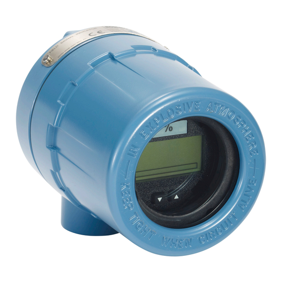
Field signal indicator
Hide thumbs
Also See for Rosemount 751:
- Quick start manual (28 pages) ,
- Reference manual (18 pages) ,
- Quick start manual (24 pages)

Subscribe to Our Youtube Channel
Related Manuals for Emerson Rosemount 751


Summary of Contents for Emerson Rosemount 751
- Page 1 Reference Manual 00809-0100-4378, Rev CG April 2024 Rosemount ™ 751 Field Signal Indicator...
- Page 2 Read this manual before working with the product. For personal and system safety, and for optimum product performance, ensure the contents are thoroughly understood before installing, using, or maintaining this product. For equipment and service needs, contact your local Emerson representative or go to Emerson.com. CAUTION The products described in this document are NOT designed for nuclear-qualified applications.
-
Page 3: Table Of Contents
Contents Chapter 1 Introduction..........................5 1.1 Product overview.........................5 1.2 LCD display........................... 5 1.3 Service support..........................5 1.4 Product recycling/disposal......................6 Chapter 2 Installation..........................7 2.1 Assembly............................7 2.2 Wiring diagrams.......................... 8 2.3 LCD display configuration......................12 Appendix A Reference data........................15 A.1 Product Certifications....................... 15 A.2 Ordering information, specifications, and drawings............15 Emerson.com/Rosemount... - Page 4 Contents Reference Manual April 2024 00809-0100-4378 Emerson.com/Rosemount...
-
Page 5: Chapter 1 Introduction
Rosemount indicators are ideal for installations where an integral meter would be difficult to view. Rosemount 751 Indicators are designed for use in industrial environments where all- weather performance is necessary. These units are vibration- and corrosion-resistant, and can be ordered with explosion-proof or intrinsically safe certifications. -
Page 6: Product Recycling/Disposal
Returned products must include a copy of the required Safety Data Sheet (SDS) for each substance. Emerson representatives will explain the additional information and procedures necessary to return goods exposed to hazardous substances. -
Page 7: Chapter 2 Installation
Figure 2-1. The meter sub-assembly contains the components shown in Figure 2-2. Figure 2-1: Rosemount 751 Exploded View A. Terminal screws B. Housing O-ring C. Field wiring terminals D. Loop protection diode E. Tapped mounting boss F. -
Page 8: Wiring Diagrams
Rosemount transmitters. Use shielded cable for best results in electrically noisy environments. Series configuration It is recommended that the 751 Indicator be wired in a series configuration when the 4-20 mA transmitter does not contain a test terminal. The indicator is designed so the LCD Emerson.com/Rosemount... - Page 9 751 Series Wiring Diagrams for Rosemount 3144P and 2051 ™ + − + − − 3144P 2051 − − 4–20 mA DC Input Signal for Rosemount 3144P 4–20 DC Input Signal for Rosemount 2051 A. Power supply B. Load resistor C. Optional ground Emerson.com/Rosemount...
- Page 10 751 Series Wiring Diagrams for Rosemount 3051 and 3051S ™ + − + − 3051S − 3051 − − − 4–20 mA DC Input Signal for Rosemount 3051 4–20 DC Input Signal for Rosemount 3051S A. Power supply B. Load resistor C. Optional ground Emerson.com/Rosemount...
- Page 11 Figure 2-5: Rosemount 751 Parallel Wiring Diagrams for Rosemont 3144P and 2051 ™ 2051 3144P 4–20 mA DC Input Signal for Rosemount 3144P 4–20 DC Input Signal for Rosemount 2051 A. Power supply B. Load resistor C. Optional ground Emerson.com/Rosemount...
-
Page 12: Lcd Display Configuration
Unscrew and remove the transparent housing cover from the LCD display body. Note The LCD display time-out is approximately 16 seconds. If you do not press the configuration buttons within 16 seconds, the indicator will revert to reading the current signal. Emerson.com/Rosemount... - Page 13 Press both configuration buttons simultaneously for two seconds. Note The meter displays “- -” for approximately 7.5 seconds while the information is being stored. 2.3.4 Set the display equivalent to a 4 mA signal Procedure 1. Press the left configuration button for two seconds. Emerson.com/Rosemount...
- Page 14 3. To store the information, simultaneously press both configuration buttons for two seconds. The LCD display meter is now configured. 2.3.6 Replace the cover Procedure Ensure the rubber gasket is seated properly, and thread the transparent housing cover onto the LCD display meter body. Emerson.com/Rosemount...
-
Page 15: Appendix A Reference Data
To view current Rosemount 751 Field Signal Indicator Product Certifications, follow these ™ steps: Procedure Emerson.com/Rosemount/Rosemount 751 Field Signal Indicator. 2. Scroll as needed to the green menu bar and click Documents & Drawings. 3. Click Manuals & Guides. 4. Select the appropriate Quick Start Guide. - Page 16 Emerson Terms and Conditions of Sale are available upon request. The Emerson logo is a trademark and service mark of Emerson Electric Co. Rosemount is a mark of one of the Emerson family of companies. All other marks are the property of their respective owners.
Need help?
Do you have a question about the Rosemount 751 and is the answer not in the manual?
Questions and answers