TESTO 6383 Instruction Manual
Differential pressure transmitter, p2a software. parameterizing, adjusting and analyzing software
Hide thumbs
Also See for 6383:
- Instruction manual (140 pages) ,
- Instruction manual (88 pages) ,
- Instruction manual (64 pages)

Related Manuals for TESTO 6383


Summary of Contents for TESTO 6383
- Page 1 6383 · differential pressure transmitter P2A software · Parameterizing, adjusting and analyzing software Instruction manual...
-
Page 3: Safety And The Environment
Pos: 8 /TD/Sicherheit und Umwelt/Sicherheit gewährleisten/MUF 63xx/Fachpersonal @ 3\mod_1234794940409_79.docx @ 26337 @ @ 1 Any additional work must only be carried out by authorized personnel. Otherwise testo will not accept any responsibility for the proper functioning of the instrument after repair and for the validity of certifications. -
Page 4: About This Document
2 About this document Pos: 11 /TD/Überschriften/MUF/1 Zu diesem Dokument @ 3\mod_1234793991331_79.docx @ 26242 @ 1 @ 1 About this document Pos: 12 /TD/Sicherheit und Umwelt/Zu diesem Dokument/Verwendung/Verwendung (Standard) @ 0\mod_1173775068554_79.docx @ 337 @ 5 @ 1 > Please read this documentation through carefully and familiarize yourself with the product before putting it to use. -
Page 5: Table Of Contents
Password protection ..................26 4.4.3. Structure of user menu .................. 26 4.4.4. Overview of the testo 6383 user menu ............28 4.4.5. The individual main menus ................30 4.4.5.1. Editing main menu of channel 1............30 4.4.5.2. Editing Main Menu Alarm ..............31 4.4.5.3. - Page 6 Tips and assistance ................69 6.1. Questions and answers ..............69 6.2. Accessories and spare parts ............69 6.2.1. Ordering options for testo 6383 transmitter (0555 6383) ........ 70 Pos: 18 /TD/--- Seitenwechsel --- @ 0\mod_1173774430601_0.docx @ 283 @ @ 1...
-
Page 7: Transmitter
Pos: 20 /TD/Überschriften/MUF/4.1/5.1/6.1 Leistungsbeschreibung @ 3\mod_1234258595211_79.docx @ 23951 @ 2 @ 1 4.1. Specifications Pos: 21 /TD/Leistungsbeschreibung/Verwendung/MUF63xx/MUF 6383,84 @ 4\mod_1251793491331_79.docx @ 47763 @ 3 @ 1 4.1.1. Functions and use The testo 6383 transmitter is suitable for the following applications, amongst others: •... - Page 8 200 hPa Upon delivery and following a factory reset the readings are shown in the display in the unit that was ordered via the KMAT option Fxx, see Ordering options for testo 6383 transmitter (0555 6383), page 70. Meas. cycle •...
- Page 9 4 Transmitter • optional: Ethernet interface Voltage supply • 4-wire (separate signal and supply lines): 20 to 30 V AC/DC, 300 mA power consumption Maximum load • 4-wire: 500 Ω (power output) Maximal load • 4-wire: 10 kΩ (voltage output) Analog output •...
- Page 10 Metal/plastic, approx. 0.9 kg Protection class, frontal • IP 65 only if the transmitter is wired and/or sealing plugs are inserted Directives, standards and tests • EC Directive: 2004/108/EC Warranty • Duration: 2 years • Warranty conditions: see website www.testo.com/warranty...
-
Page 11: Dimensions
4 Transmitter Pos: 25 /TD/Leistungsbeschreibung/Technische Daten/MUF 63xx/MUF Panel kurz Abmessungen @ 4\mod_1251817616346_79.docx @ 47923 @ 3 @ 4 4.1.5. Dimensions... -
Page 12: Product Description
4 Transmitter Pos: 26 /TD/Überschriften/MUF/5.2/6.2 Produktbeschreibung @ 3\mod_1234258723551_79.docx @ 24008 @ 2 @ 1 4.2. Product description Pos: 27 /TD/Produktbeschreibung/Übersicht/MUF 63xx/Auf einen Blick 6384 @ 4\mod_1251709849283_79.docx @ 47729 @ 3 @ 4 4.2.1. At a glance 1 Sealing plugs on the positive pressure test connection (Ø... -
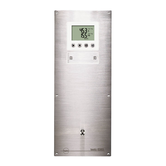
Page 13: Display And Keypad
Pos: 28 /TD/Produktbeschreibung/Übersicht/MUF 63xx/Display und Tastatur @ 3\mod_1234773965059_79.docx @ 25650 @ 3 @ 1 4.2.2. Display and keypad The display option allows operation of the testo 6383 transmitter via the display and four keys. The LCD display consists of two 7-segment lines for displaying readings and units and of an information line (for status messages, for example). -
Page 14: Relay Board (Option)
Pos: 32 /TD/Produktbeschreibung/Übersicht/MUF 63xx/Analogausgänge 635x @ 3\mod_1234774510463_79.docx @ 25726 @ 3 @ 1 4.2.5. Analog outputs As analog outputs, the testo 6383 has either • 1 current output of 0 to 20 mA (4-wire)/4 to 20 mA (4-wire) or •... -
Page 15: Alarm Handling
The testo 6383 monitors limit values with the help of relays. If a reading is outside the limit values, a relay to be specified by the user is switched. -
Page 16: Commissioning
4 Transmitter If multiple alarm messages are activated at the same time, the last alarm is shown. If the alarm is cancelled again, the previous messages are no longer shown. Pos: 37 /TD/Überschriften/MUF/4.3/5.3 Inbetriebnahme @ 3\mod_1234258805768_79.docx @ 24027 @ 2 @ 1 4.3. -
Page 17: Connecting The Instrument
> De-energize the mains connection before connecting the transmitter. Only have the transmitter wired and connected by authorized personnel with the voltage disconnected. Pos: 40 /TD/Erste Schritte/MUF 63xx/Anschlussübersicht 6383 @ 4\mod_1251708327447_79.docx @ 47697 @ 4 @ 4 4.3.2.1. Overview of terminals 1 Terminal strip for voltage... -
Page 18: Connecting Voltage Supply And Analog Outputs
4 Transmitter Pos: 41 /TD/Erste Schritte/MUF 63xx/Spannungsversorgung/Analogausgänge anschließen 6384/6386 @ 4\mod_1255072485688_79.docx @ 51663 @ 45 @ 1 4.3.2.2. Connecting voltage supply and analog outputs Terminal strip for voltage supply and analog outputs, item (1) of overview of terminals Channels 2 and 3 shown on the pin assignment plan cannot be used with this instrument. -
Page 19: Connecting The Relay Outputs
4 Transmitter 3. Tie together each of the two adjacent cores using a cable tie. 4. Attach terminal strip for voltage supply and analog outputs. Pos: 42 /TD/Erste Schritte/MUF 63xx/Relaisausgänge anschließen Panel @ 4\mod_1251814425917_79.docx @ 47891 @ 4555 @ 1 4.3.2.3. - Page 20 4 Transmitter • The insulation of the cable must be fed at least 5 mm (4) into the relay tray up to the elevated part. Use of relay as NC contact (NC = normally closed) 1 Alarm/status light (example of installation) 2 250 V AC/DC, 3 A The busy light (alarm/status light) is permanently on until the relay opens or the circuit is interrupted.
- Page 21 4 Transmitter Use of relay as NO contact (NO = normally open) 1 Alarm/status light (example of installation) 2 250 V AC/DC, 3 A The busy light (alarm/status light) only comes on when the relay is switched (closed). Monitoring the functionality of the alarm circuit is therefore not possible with this switching operation.
-
Page 22: Connecting Pressure Connections
4 Transmitter Pos: 43 /TD/Erste Schritte/MUF 63xx/Druckanschlüsse anschließen @ 11\mod_1329143404035_79.docx @ 110676 @ 455 @ 4 4.3.2.4. Connecting pressure connections Illustration shows delivery status Use of front pressure connection 1. Remove hose from hose holder (2) and connect to overpressure (3) or underpressure (1) connection. 2. -
Page 23: Closing The Instrument
Pos: 44 /TD/Erste Schritte/MUF 63xx/Gerät schließen 6384 @ 4\mod_1252311705538_79.docx @ 48381 @ 4 @ 4 4.3.2.5. Closing the instrument 1. Pull sealing frame (1) over the edge of the 6383. 2. Screw on 6383. Initially, only tighten the screws slightly. When all screws are in position, also align 6383 and tighten the screws. - Page 24 3. Contact ch. 3 (non-functional) 4. Service interface Adjusting analog output 1 ✓ With testo 6383 with current output: Load of max. 500 Ω is connected to channel 1. ✓ A precise multimeter (minimum requirement: resolution 6.5 digits, at least 5-times more accurate than the 6383) is available.
-
Page 25: N-Point Adjustment
✓ A precise pressure sensor (5-times more accurate than the transmitter, e.g. DPC precision pressure sensor from testo industrial services) is available. 1. Connect the positive output of the pressure sensor (3) to the... -
Page 26: Operation
4.4.1. Relationship between user menu and mini-DIN socket is active The testo 6383 can be parameterized using either the user menu or the P2A software (see Parameterizing, adjusting and analyzing software (P2A software) page 44). The testo 6383 transmitter can only be operated via the display and keypad if the display option is available. - Page 27 4 Transmitter 1 Channel 1 display 2 No display 3 Display for messages Four keys enable the user to navigate/scroll through the menus and enter/amend values and settings: Function/description • In Measuring Mode: changes to parameterization • In Parameterizing Mode: confirms a selection or setting •...
-
Page 28: Overview Of The Testo 6383 User Menu
4 Transmitter Pos: 52 /TD/Produkt verwenden/MUF 63xx/Übersicht Bedienmenü @ 3\mod_1234510821302_79.docx @ 25303 @ 3 @ 1 4.4.4. Overview of the testo 6383 user menu... - Page 29 4 Transmitter...
-
Page 30: The Individual Main Menus
The individual main menus 4.4.5.1. Editing main menu of channel 1 An overview is given in Overview of the testo 6383 user menu, page 28). You can perform basic settings for channel 1. 1. In the Measuring Mode press SET, select... -
Page 31: Editing Main Menu Alarm
4 Transmitter Pos: 54 /TD/Produkt verwenden/MUF 63xx/Hauptmenü Alarm bearbeiten 635x @ 4\mod_1245756301576_79.docx @ 45273 @ 455 @ 1 4.4.5.2. Editing Main Menu Alarm With the alarm, the relays, available as options, are programmed. In addition, the alarm statuses are shown on the display (top right) (even without relays). -
Page 32: Editing Main Menu Settings
If an alarm is assigned to the collective alarm, the relay is switched and a visual alarm can be issued via the display as soon as (at least) one of the warning or error messages of the testo 6383 transmitter becomes active. - Page 33 4 Transmitter • Display • Language • Change unit ◦ Absolute pressure ◦ Temperature • Code Editing display settings You can set the brightness and contrast of the display. with or and confirm selection with 1. Select Display Settings SET.
-
Page 34: Editing Main Menu Analysis
4 Transmitter Editing code settings You can set the access code (password). If a code other than "0000" (factory setting) is set, the transmitter can only be operated once this code has been entered via the menu. 1. Select Code with ... - Page 35 4 Transmitter 3. Accept setting by pressing and test with multimeter (minimum requirement: resolution 6.5 digits, at least 2-times more accurate than the 6383) as follows: Analog output 1: Via test contacts under service flap, see diagram. 1 Channel 1...
-
Page 36: Editing Message Main Menu
4 Transmitter 2. Continue to Main Menu Message with or or return to Measuring Mode with ESC. Pos: 57 /TD/Produkt verwenden/MUF 63xx/Hauptmenü Meldungen bearbeiten @ 3\mod_1234526541417_79.docx @ 25398 @ 4 @ 1 4.4.5.5. Editing Message main menu Messages can be confirmed/acknowledged, the last messages can be called up and the display of the messages can be switched on or off. -
Page 37: Calling Up Main Menu Ident
4 Transmitter 9. Return to Main Menu Message with ESC. with or or return to 10. Continue to Main Menu Ident Measuring Mode with ESC. An overview of the messages can be found in Status, warning and error messages, page 39 Pos: 58 /TD/Produkt verwenden/MUF 63xx/Hauptmenü... - Page 38 4 Transmitter 3. Use or to select Adj. Point 4. Press SET. Read off multimeter display and enter this value in the user menu. Do this by scrolling one digit to the right using and increasing the value of digit by 1 using . Confirm with or abort entry with ESC.
-
Page 39: Editing Reset Main Menu
Warning messages • Error messages in each case for the testo 6383 transmitter. All messages are stored in the transmitter with an operating hours stamp. Use the user menu (see Editing Message main menu, page 36) or the P2A software (see Transmitter history, page 65) to view the message history. -
Page 40: Status Messages
4 Transmitter Pos: 63 /TD/Produkt verwenden/MUF 63xx/Status-Warnmeldungen/Statusmeldungen 635x @ 3\mod_1235651943832_79.docx @ 26823 @ 3 @ 1 4.5.1. Status messages Status messages show the current operating status of the testo 6383. Message Display Description Sensor Message appears while the 02506 initialization transmitter is starting up. -
Page 41: Warning Messages
4 Transmitter Pos: 64 /TD/Produkt verwenden/MUF 63xx/Status-Warnmeldungen/Warnmeldungen 635x @ 3\mod_1236081573428_79.docx @ 27192 @ 3 @ 1 4.5.2. Warning messages Warning messages show an early warning or a current malfunction which may negatively impact measuring. Message Display Cause Remedying of fault The ambient Take necessary 00E00... -
Page 42: Handling Alarm Messages
Cause Remedying of fault 01505 Watchdog error Due to a processor If the problem occurs error, the transmitter frequently, contact performs an automatic Testo Service. restart. 01115 Low adjustment The ambient Take necessary temperature temperature is too low measures to raise... -
Page 43: Namur Fault Conditions
4 Transmitter Shown on the Can be used for Additional display collective alarm message end Analog adjustment T ambient high T ambient low Supply voltage low Watchdog error Perform the Confirm message function (acknowledgement of the alarm via the control keys on the transmitter): •... -
Page 44: Maintenance And Cleaning
Pos: 72 /TD/Leistungsbeschreibung/Verwendung/MUF63xx/MUF 63xx P2A @ 3\mod_1234258967326_79.docx @ 24065 @ 355 @ 1 The P2A software is used for the parameterizing, adjustment and analysis of testo transmitters. The following applies: • Generally, all newer testo transmitters (as of 2007) are supported. • For each newly purchased Testo transmitter, a free software upgrade must be installed, containing the instrument drivers for all transmitters which are connectable at that time. -
Page 45: Functions And Use
5 Parameterizing, adjusting and analyzing software (P2A software) The software must only be bought one time, even for owners of several testo transmitters. 5.1.1. Functions and use In the P2A software, two different file types are used: The instrument and the parameter file. -
Page 46: Scope Of Delivery
5 Parameterizing, adjusting and analyzing software (P2A software) Date and time settings are automatically taken over from the computer. The administrator must ensure that the system time is regularly synchronized with a reliable time source, in order to guarantee the authenticity of the data. Software The P2A software must be purchased and installed separately from the transmitter. -
Page 47: P2A Software Upgrade
5 Parameterizing, adjusting and analyzing software (P2A software) 5.2.1.3. P2A software upgrade 1. Download and store P2A software upgrade from www.testo.com/download-center (requires registration). 2. Select folder into which the downloaded Zip file was stored, and unzip the file. 3. Start file upgrade.exe. -
Page 48: Activating The Connection With The Instrument
5 Parameterizing, adjusting and analyzing software (P2A software) 5.2.2.3. Activating the connection with the instrument > Click on the desired instrument file. The selected file is marked in colour and the connection with the instrument is activated. If a connection with the instrument is established when the program is started, the corresponding instrument file is marked automatically. - Page 49 5 Parameterizing, adjusting and analyzing software (P2A software) Menu Command Explanation Paste Pastes the parameters from the cache in the marked instrument or parameter file. View Toolbar Activates/deactivates the toolbar or status bar. Status bar Check instrument Checks the connections to a connections connected instrument without the instrument having to be...
- Page 50 5 Parameterizing, adjusting and analyzing software (P2A software) Icon File Explanation Parameter <Type> <Serial number> file <Date> <Time>.cfp Symbol shows a transmitter with a white File name can be changed. P for parameter file in The name can be selected freely, the upper left corner but it is recommended that you retain the reference to the...
-
Page 51: Editing Instrument/Parameter File
5 Parameterizing, adjusting and analyzing software (P2A software) Pos: 80 /TD/Produkt verwenden/MUF 63xx/P2A/Geräte-/Parameterdatei bearbeiten @ 3\mod_1234358080444_79.docx @ 24303 @ 34 @ 1 5.3.2. Editing instrument/parameter file 5.3.2.1. Changing instrument/parameter file ✓ The desired instrument/parameter file is marked. 1. Click on [Change parameterization]. - Page 52 5 Parameterizing, adjusting and analyzing software (P2A software) Field Explanation Unit/analog output Unit: 0 to 1 V/5 V/10 V or 0 to 20 mA/4 to (graphic) 20 mA. Vertical: Current version of the analog output (cannot be changed). Horizontal: Min./max. scale end points of selected unit.
- Page 53 5 Parameterizing, adjusting and analyzing software (P2A software) Pos: 82 /TD/Produkt verwenden/MUF 63xx/P2A/Grenzwerte Relais @ 3\mod_1234366741293_79.docx @ 24611 @ @ 1 Field Explanation Limit values, relay 1 to 4/alarm In this mask, the relays or display values, alarm 1 to 4 alarms are parameterized.
- Page 54 5 Parameterizing, adjusting and analyzing software (P2A software) Field Explanation Max control If switched to ON (NO contact) or OFF (NC contact) above the limit value; in the event of a subsequent undershooting of Limit value minus Hysteresis, it is switched to OFF (NO contact) or ON (NC contact).
- Page 55 5 Parameterizing, adjusting and analyzing software (P2A software) Field Explanation Alarm delay The desired alarm delay for the alarms of the min/max control and the visual alarm is entered in the input field (0 to 3600 seconds possible). The alarm delay has no effect on the collective alarms.
- Page 56 5 Parameterizing, adjusting and analyzing software (P2A software) Field Explanation Display of the error Selection of whether the error messages messages should be shown in the display. Display language Selection of the language. New password The password consists of four numbers, each of which must be between 1 and 9.
-
Page 57: Saving Parameters
The original name (Instrument type, Serial number) is suggested with the current date/time as standard, e.g. "testo 6383 01234578 061120 1403.cfp". For a standard installation, the files are saved under "C:\Documents and Settings\All Users\Shared Documents\P2A Software". The path can differ depending on the version of the operating system. -
Page 58: Copying And Pasting Parameters
5 Parameterizing, adjusting and analyzing software (P2A software) Pos: 87 /TD/Produkt verwenden/MUF 63xx/P2A/Parameter kopieren/einfügen @ 3\mod_1234358826054_79.docx @ 24360 @ 4 @ 1 5.3.2.4. Copying and pasting parameters The parameters of a parameter file can be transmitted to an instrument file or another parameter file from the same instrument type. -
Page 59: Analyzing/Testing The Instrument
5 Parameterizing, adjusting and analyzing software (P2A software) 5.3.3.1. Analyzing/testing the instrument ✓ The required instrument file is marked. 1. Click on [Test/analyze transmitter]. Properties of <Instrument type> <Serial number> dialogue is opened with the Test/analyze transmitter register. 2. Perform action: Action Explanation Carrying out factory... - Page 60 5 Parameterizing, adjusting and analyzing software (P2A software) Field/button Explanation Check the analog outputs (see Testing Transmitter test functionality of analog outputs, page 34). Current reading Readings are updated every second. Unit Unit according to the type of analog output. Default value Freely definable output value for the respective type of analog output (V or...
-
Page 61: Testing Switch Output Relays 1 To 4
5 Parameterizing, adjusting and analyzing software (P2A software) 3. Click on [OK] [Cancel] to close the dialogue. The analog output and the relay return to Measuring Mode again. Pos: 94 /TD/Produkt verwenden/MUF 63xx/P2A/Schaltausgang Relais testen 635x @ 3\mod_1237374457598_79.docx @ 29866 @ 4 @ 1 5.3.3.4. -
Page 62: Displaying Min./Max. Values
5 Parameterizing, adjusting and analyzing software (P2A software) Pos: 95 /TD/Produkt verwenden/MUF 63xx/P2A/Min-/Max-Werte anzeigen 635x @ 3\mod_1242135985269_79.docx @ 32803 @ 4 @ 1 5.3.3.5. Displaying min./max. values The transmitter saves the minimum or maximum value for each channel (measured since the last voltage supply or since the last manual reset). -
Page 63: Adjusting The Transmitter
5 Parameterizing, adjusting and analyzing software (P2A software) Pos: 96 /TD/Überschriften/MUF/x.x.x Messumformer abgleichen @ 4\mod_1244530152797_79.docx @ 44885 @ 3 @ 1 5.3.4. Adjusting the transmitter Pos: 97 /TD/Produkt verwenden/MUF 63xx/P2A/Messumformer abgleichen 635x @ 3\mod_1235996515230_79.docx @ 27024 @ @ 1 This function is used to adjust an attached instrument. The following adjustments may be carried out using the software: •... -
Page 64: Adjusting The Analog Output
5 Parameterizing, adjusting and analyzing software (P2A software) Field Explanation How much pressure Required field: Entry of the value read off at is actually applied the pressure sensor. The n-point adjustment must always be carried out to its full extent and in good time at all selected adjustment points. The number of adjustment points (3 to 6) is stored in the user menu of the transmitter and can only be changed via the P2A software. -
Page 65: Transmitter History
5 Parameterizing, adjusting and analyzing software (P2A software) Field Explanation Default value The analog output value from the last performed adjustment is given at the output. Value of the factory adjustment: • Lower adjustment point: approx. 10 % of the max. value •... - Page 66 5 Parameterizing, adjusting and analyzing software (P2A software) 3. Click on the required entry in the list to change the display. Field Explanation Operating hours / Operating hour/time stamp at which the date/time change at the instrument was performed. User Name with which the user is logged into the operating system.
- Page 67 5 Parameterizing, adjusting and analyzing software (P2A software) Field Explanation Selection: Analog adjustments. Operating hours / Operating hour/time stamp at which the date/time change at the instrument was performed. Name with which the user is logged into the User operating system. "Transmitter"...
- Page 68 5 Parameterizing, adjusting and analyzing software (P2A software) Field Explanation The table is shown only for error and status messages that were generated in the transmitter and were transferred and saved there via the connection to the P2A software. Operating hour Operating hour at which the message appeared in the instrument.
-
Page 69: Tips And Assistance
If we could not answer your question, please contact your dealer or Testo Customer Service. For contact details see the rear side of this document or the web page www.testo.com/service-contact Pos: 105 /TD/Überschriften/8.2 Zubehör und Ersatzteile @ 0\mod_1177402058734_79.docx @ 1102 @ 2 @ 1 6.2. -
Page 70: Ordering Options For Testo 6383 Transmitter (0555 6383)
For a complete list of all accessories and spare parts, please refer to the product catalogues and brochures or look up our website at: www.testo.com Pos: 107 /TD/Tipps und Hilfe/Zubehör und Ersatzteile/MUF63xx/Bestelloptionen MUF 6383 @ 4\mod_1251701200773_79.docx @ 47633 @ 3 @ 1 6.2.1. Ordering options for testo 6383 transmitter (0555... - Page 71 With display/Italian With display/Japanese With display/Swedish Dxx Integrated humidity probe No humidity/temperature probe Humidity/temperature probe integrated in panel Preparation for external humidity/temperature probe testo 6610 probe Exx Ethernet Without Ethernet interface With Ethernet interface Fxx Differential pressure unit Pa/Min/Max hPa/Min/Max...
- Page 72 6 Tips and assistance Order code Characteristic inch HG/Min/Max kg/cm /Min/Max PSI/Min/Max Gxx Optional analog output for humidity probe connection testo 6610/units % RH/Min/Max °C/Min/Max °F/Min/Max °C /Min/Max °F /Min/Max g/kg /Min/Max gr/lb /Min/Max /Min/Max gr/ft /Min/Max ppmV/Min/Max °C /Min/Max °F...
- Page 73 6 Tips and assistance Order code Characteristic 4 relay outputs, channel 1 limit values and collective alarm Ixx Units, channel 3 (only if optional humidity probe connection is available) % RH/Min/Max °C/Min/Max °F/Min/Max °C /Min/Max °F /Min/Max g/kg /Min/Max gr/lb /Min/Max /Min/Max gr/ft /Min/Max...
- Page 74 6 Tips and assistance...
- Page 75 6 Tips and assistance...
- Page 76 0970 6384 en 02 V01.12 V01.70-1 en...
Need help?
Do you have a question about the 6383 and is the answer not in the manual?
Questions and answers