
Related Manuals for CNC4PC C52- ESS


Summary of Contents for CNC4PC C52- ESS
- Page 1 USER’S MANUAL VER.2.2 C52- ESS THIRD PORT EXPANSION BOARD Rev. 2 JUNE, 2019 ___________________________________________________________________________ User’s Manual Page i...
-
Page 2: Table Of Contents
USER'S MANUAL TABLE OF CONTENTS Page # 1. OVERVIEW ........................... 1 2. FEATURES ........................... 1 3. I/O SPECIFICATIONS ......................2 4. BOARD DESCRIPTION ......................2 5. POWER PIN ........................... 3 6. JUMPER SELECTION ......................4 Input 5V ........................4 Input 12V / 24V ......................4 Select JUMPER COM for the inputs................ -
Page 3: Overview
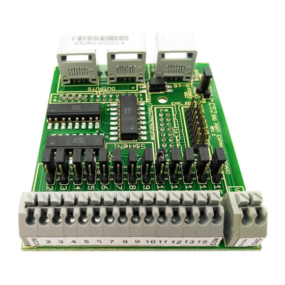
1. OVERVIEW This card provides an easy way of interfacing your inputs and outputs from your Ethernet Smooth Stepper third port. It provides terminals for the connections and conditions the signals for use in CNC applications. You can connect other boards using the standard RJ45 cables. -
Page 4: I/O Specifications
3. I/O SPECIFICATIONS OPTOISOLATED DIGITAL INPUT SPECIFICATIONS On-state voltage range 3 to 5V DC Maximum off-state voltage 0.8V Maximum operation frequency 4 MHz Typical signal delay Less than 500uS DIGITAL OUTPUT SPECIFICATIONS (5V power supply voltage) + 0.5V Maximum output voltage Typical output current 24mA Maximum off-state voltage... -
Page 5: Power Pin
5. POWER PIN This board is polarized by pin 26 of IDC26 with 5V, provided by the ESS Note: Make sure that the ESS jumper is on, as shown in the picture User’s Manual Page 3... -
Page 6: Jumper Selection
6. JUMPER SELECTION Input 5V Input 12V / 24V User’s Manual Page 4... -
Page 7: Select Jumper Com For The Inputs
Select JUMPER COM for the inputs Set the Jumper to COM = +5VDC, GND or 12VDC / 24VDC to determine the common for the input signals to be used. COM = 5V COM = GND with 5V COM = GND with 12VDC / 24VDC User’s Manual Page 5... - Page 8 User’s Manual Page 6...
-
Page 9: Isolate Input
COM = 12V / 24V Isolate Input User’s Manual Page 7... -
Page 10: Pinout
7. PINOUT Connectors RJ45 This board supports only TTL +5VDC signals. Table below shows the supported connections for each RJ45. RJ45_1 RJ45_2 RJ45_3 RJ45 PIN P.P. PIN RJ45 PIN P.P. PIN RJ45 PIN P.P. PIN 3_17 Not Used 3_16 Not Used 3_16 3_14 3_17... -
Page 11: Dimensions
8 DIMENSIONS All dimensions are in Millimeters. Fixing holes (3.8mm) DISCLAIMER: Use caution. CNC machines can be dangerous machines. Neither DUNCAN USA, LLC nor Arturo Duncan are liable for any accidents resulting from the improper use of these devices. This product is not a fail-safe device and it should not be used in life support systems or in other devices where its failure or possible erratic operation could cause property damage, bodily injury or loss of life.
Need help?
Do you have a question about the C52- ESS and is the answer not in the manual?
Questions and answers