Table of Contents
Advertisement
Quick Links
Advertisement
Table of Contents

Summary of Contents for SPX SPIDAR NIC-500s
- Page 3 Warranty Confirmation Warranty Confirmation Return this card within 60 days of purchase to confirm your warranty. You can mail it to Sensors & Software, fax it to +1-905-624-9365, or register your product online at www.sensoft.ca/product-registration. Name: Company Name: Address: City: State/Province: Zip Code: Country:...
- Page 4 Warranty Confirmation...
- Page 5 End User License Agreement Please read the End User License Agreement at https://www.sensoft.ca/producteula/ Product Warranty and Limited Liability Please refer to the terms and conditions included as part of your order acknowledgement and/or invoice for full details of the product warranty and limited liability. Important Safety Information Read this manual in its entirety before attempting to operate the SPIDAR system.
- Page 7 Table of Contents Introduction......................1 Overview of NIC-500s .................... 3 NIC-500N NIC-500P NIC-500X Getting Started ....................... 9 Connecting all components – Single NIC-500 Connecting all components – multiple NIC-500s GPS (optional) Powering up Connecting your device to the NIC-500 Powering down NIC-500 SPIDAR Software ....................
-
Page 8: Table Of Contents
Table of Contents Appendix A: Data Collection Modes ................83 Appendix B: Components ....................85 Appendix C: Calculating GPS Latency ................87 Appendix D: GPR Knowledge ..................93 Appendix E: Port Specifications ..................95 Appendix F: Health & Safety Certification ..............97 Appendix G: GPR Emissions, Interference and Regulations ......... - Page 9 Introduction Introduction Congratulations on your purchase of SPIDAR. The SPIDAR NIC-500s are a family of devices used to connect multiple GPR systems and create a custom platform to address a wide range of GPR applications. The variety of available configurations allow for a truly customizable multi- channel system.
- Page 10 Introduction...
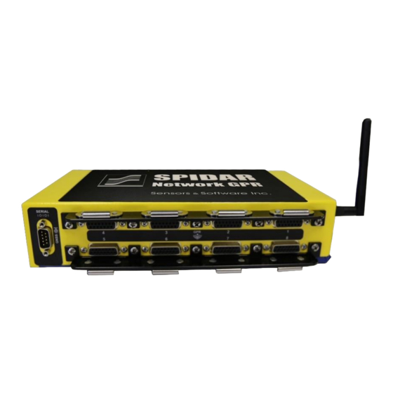
- Page 11 Overview of NIC-500s Overview of NIC-500s This section explains the physical properties of the NIC-500s. Attributes common to all NIC- 500s are explained, followed by differences between NIC-500N, NIC-500P and NIC-500X. Figure 2-1: SPIDAR NIC-500 A NIC (short for Network Interface Controller) is a device that allows users to collect data with multiple GPR antennas simultaneously (Figure 2-1).
- Page 12 Overview of NIC-500s updated by inserting a USB containing the upgrade file into one of these ports (Section 4.6.1) • Ethernet– there are two Ethernet ports. If you are using a hardware connection to the NIC-500, then you must run an Ethernet cable between your device and the NIC-500. If you are daisy-chaining NIC-500s, you must plug an Ethernet cable from one NIC-500 to...
- Page 13 Overview of NIC-500s Figure 2-3: Showing the front (short) side of the NIC-500 2.1 NIC-500N A NIC-500N is a variation of the NIC that can be used to run up to 2 Noggins simultaneously. Noggins are available in 4 center frequencies: 100, 250, 500 and 1000 MHz. Multiple NIC- 500Ns can be connected together, to run any number of Noggin systems;...
- Page 14 Overview of NIC-500s Figure 2-4: Long side of NIC-500N showing Noggin ports and serial port 2.2 NIC-500P The NIC-500P can run up to 2 pairs of pulseEKKO PRO transmitters and receivers simultaneously. pulseEKKO PRO antennas are available in 8 center frequencies: 12.5, 25, 50, 100, 200, 250, 500 and 1000 MHz.
- Page 15 Overview of NIC-500s Figure 2-5: Long side of NIC-500P showing pulseEKKO antenna ports and serial port Figure 2-6: Fibre optic converters 2.3 NIC-500X The NIC-500X allows for the connection of up to eight pulseEKKO PRO transmitters and receivers simultaneously. The key distinction compared to the NIC-500P is that any combination of transmitters and receivers can be connected to the NIC-500X.
- Page 16 Overview of NIC-500s Figure 2-7: Long side of NIC-500X showing pulseEKKO antenna ports and serial port On the long side of the NIC-500X (opposite side of the power and odometer connections), there are eight pulseEKKO ports and a serial port (Figure 2-7), described below: •...
- Page 17 Getting Started 3. Getting Started This section explains how to connect all the components of the NIC-500 together. The first step is identifying the required cables. Depending on the setup, the cables displayed in Figure 3-1 may not all be needed. Figure 3-1: Common NIC cables •...
- Page 18 Getting Started Figure 3-2: pulseEKKO PRO power cable, not included with NIC-500s, but could be used to power a single NIC-500 3.1 Connecting all components – Single NIC-500 This section describes the cable connections to and from a NIC-500. Refer to Chapter 2 information on NIC-500 ports.
- Page 19 Getting Started Figure 3-3: Plugging in cables to a NIC-500 Figure 3-4: Connecting a GPS receiver to the serial port The sections below explain the antenna cable connections for each type of NIC-500. 3.1.1 NIC-500N Up to two Noggin systems can be plugged into the Noggin ports on a single NIC-500. The ports are numbered ‘1’...
- Page 20 Getting Started Figure 3-5: Connecting Noggin cables to the NIC-500N Once completed, move on to Powering up in Section 3.4. 3.1.2 NIC-500P Up to two pairs of pulseEKKO PRO antennas can be plugged into the pulseEKKO ports on the NIC-500. These ports are numbered ‘1’, ‘2’, ‘3’ and ‘4’. Note that ports ‘1’ and ‘3’ should be used for transmitters and ports ‘2’...
- Page 21 Getting Started 3.1.3 NIC-500X The NIC-500X allows for the connection of up to eight pulseEKKO PRO transmitters and receivers simultaneously. The key distinction compared to the NIC-500P is that any combination of transmitters and receivers can be connected to the NIC-500X. For example, various configurations include 1 transmitter and 7 receivers, 1 transmitter and 5 receivers, and 4 transmitters and 4 receivers.
- Page 22 Getting Started • connect the Ethernet cable from the Ethernet port of one NIC-500 to the Ethernet port of the other NIC-500; it doesn’t matter which Ethernet port is used. • connect the NIC Sync cable from the Link Out of the Master NIC-500 to the Link In of the subordinate NIC-500.
- Page 23 Getting Started serial port on the NIC-500 (Figure 3-9). If the systems are daisy-chained, the GPS must be connected to the Master NIC-500. Figure 3-9: Connecting cable at GPS end (L) and at NIC-500 end (R) To connect and utilize a 3 party GPS with the NIC-500, it must meet the following criteria: •...
- Page 24 Getting Started 3.4 Powering up Once all connections are made, connect the NIC power cable to the battery. Press the Power button to turn on the NIC-500 (Figure 3-10). Figure 3-10: Front of NIC-500 showing power button and LCD Display Once the NIC-500 has powered up (about 30 seconds), the network name of the NIC-500 will be displayed on the top line of the LCD display;...
- Page 25 Getting Started Operating System: Windows 7 or 10, Android or Linux Web Browser: Google Chrome (version # 61.0.3163.100 or later) Display Screen: 10-inch or larger is recommended Resolution: 1920 x 1200 is recommended Wireless Connection To connect wirelessly from the device to the NIC-500, first obtain the name of the NIC-500 network from the LCD display.
- Page 26 Getting Started Figure 3-12: Welcome screen when you successfully connect to the NIC-500 If this screen does not appear or an error message appears (Figure 3-13), confirm that the device is indeed connected to the NIC-500 network, and not a different Wi-Fi network. In some rare cases, the device may need to be rebooted to ensure proper connectivity.
- Page 27 Getting Started 3.6 Powering down NIC-500 It is recommended to power down the NIC-500 in the software (Section 4.6.1). This ensures that the system shuts down in the proper way. In the event that the NIC-500 cannot be powered down in the software, press and hold the power button on the NIC-500 for a few seconds.
- Page 28 Getting Started...
- Page 29 SPIDAR Software 4. SPIDAR Software The SPIDAR Software allows the user to: • Configure and setup data collection parameters • Setup unique parameters for each antenna • Control data acquisition • Manage and export data from the NIC-500 During Line Scan operation, the data is displayed for the user to ensure that the system is running properly and collecting data.
- Page 30 SPIDAR Software Figure 4-2: Available options from Hamburger button or Welcome screen Below the menu options there is a slider to change the Background Theme. Using the slider, the background can be toggled between light and dark themes. This is a personal preference; however most users would likely find Dark Theme to be better suited for operation in direct sunlight.
- Page 31 SPIDAR Software Figure 4-3: Project Management screen, showing just one active project Click the + button to create a new project (you cannot use a name that already exists). A pop- up window will appear where the project name can be entered (Figure 4-4). Use letters and numbers only, special characters are not allowed.
- Page 32 SPIDAR Software Figure 4-5: Expanded view showing the lines in a project There are 3 buttons available when the project is expanded: • Download – pressing this will copy the data from that Project to the device that is connected to the NIC-500. For large volumes of data, the software may produce an error message that it is unable to download.
- Page 33 SPIDAR Software Figure 4-6: Changing downloads directory in Google Chrome • Export to USB – provided a USB stick is inserted into one of the NIC-500 USB ports, pressing this button will copy the data (.GPZ file) for that project to the USB stick. A directory structure will be created on the USB stick.
- Page 34 SPIDAR Software Figure 4-7: Project Management screen with multiple NIC-500s Menu options are limited when connecting directly to a subordinate NIC-500 (Figure 4-8). Figure 4-8: Menu options when connecting to a subordinate NIC-500 4.3 System Configuration The System Configuration menu allows the user to configure the collection parameters and positions of each connected antenna.
- Page 35 SPIDAR Software Figure 4-9: Creating, saving and deleting System Configurations Above the blue bar are buttons that allow the user to create, save and delete system configurations (Figure 4-9). These are explained below: • Current Configuration – the name of the current configuration is shown. To load a saved configuration, select it from the drop-down box.
- Page 36 SPIDAR Software Figure 4-10: NIC-500 tab in System Configuration menu 4.3.2 Antennas The antennas tab displays the transducers or antennas connected to the NIC-500s. The screen displayed will differ slightly depending on the type of NIC-500 used. Antenna Positions For all NIC-500 types, the relative position of each antenna must be entered, by inputting values for the X Position and Y Position.
- Page 37 SPIDAR Software Figure 4-11: Example of setting the offsets for 7 Noggin GPR systems on a cart. The center of the Noggin in the top left position is x=0, y=0 and all other Noggins are positioned relative to the first one. The 3 Noggins to the right would have positive X coordinates and the three Noggins at the bottom would have negative Y coordinates.
- Page 38 SPIDAR Software Based on the positions listed, the Noggin 1000 would be at the front centered on the origin (0,0), and the Noggin 500 behind it. NIC-500N – Multiple NIC-500s If the user has daisy-chained more than one NIC-500, it will list each NIC-500 and the Noggins connected to it;...
- Page 39 SPIDAR Software Figure 4-14: Antenna tab showing a single NIC-500, with two pairs of pulseEKKO antennas NIC-500P – Multiple NIC-500s If the user has daisy-chained NIC-500Ps, the page will list each NIC-500 and the pulseEKKO PRO antennas connected to it. Figure 4-15 shows two NIC-500s, where the first NIC-500 has two pairs of antennas connected, and the second NIC-500 only has one pair connected.
- Page 40 SPIDAR Software When daisy-chaining more than two NIC-500s, it is recommended to contact Sensors & Software support for advice on the port connections and physical placement of each pulseEKKO to optimize data collection. Currently, a maximum of 4 NIC-500s can be daisy- chained.
- Page 41 SPIDAR Software assigned to firing group 1; Tx , Rx and Rx are assigned to firing group 3. These two events make Sequence 1. For Sequence 2, Tx , Rx & Rx are assigned to firing group 1, and Tx , Rx &...
- Page 42 SPIDAR Software The SPIDAR screen display is shown in Figure 4-18. Figure 4-18: Two pairs of 500 MHz transmitters and receivers The user must first select the number of sequences from the drop-down box under the blue bar. This will control the number of sequence columns displayed on the right of the screen. In this case, the user has selected 2 sequences, resulting in two columns (Seq1 and Seq2) being displayed.
- Page 43 SPIDAR Software 4.3.3 The GPR tab allows the user to setup parameters specific to the connected antennas (Figure 4-19). This section describes the settings common to all NIC-500s. Figure 4-19: Setting parameters under the GPR tab Note: When using a single NIC-500 with multiple GPR units, there are some settings that must be same for the GPR units (such as step size, points per trace and stacks);...
- Page 44 SPIDAR Software The table below lists some default time windows and their associated depth of penetration, assuming a velocity of 0.1 m/ns (or 0.328 ft/ns). Frequency (MHz) Time Window (ns) Approx. Depth (m) Approx. Depth (ft) 12.5 1600 1000 1.25 Changing the time window will correspondingly change the points per trace (described below).
- Page 45 SPIDAR Software Time Sampling Interval Also known as Temporal Sampling, this defines how often the GPR wave is sampled at the GPR receiver, to accurately capture the resulting signal waveform. It is expressed as a time interval, in picoseconds, between points on a trace (1000ps = 1ns). Antenna frequency affects the sampling interval;...
- Page 46 SPIDAR Software “stacking”. Stacking improves data quality because noise, which is usually a random addition to the trace, tends to zero when averaged. The following diagram displays how data is stacked. At each data collection point, the trace is collected multiple times. Traces are averaged to calculate the resulting data trace, which is saved.
- Page 47 SPIDAR Software Figure 4-20: GPR1 & GPR2 must have the same points per trace 4.3.4 The user has the following options for configuring the GPS parameters (Figure 4-21): • GPS Device – Use this dropdown to select the External GPS or turn GPS off. If the user selects External, they can attach an optional GPS to the system via the serial cable.
- Page 48 SPIDAR Software For example, at 25 km/h, you are moving 6.94m per second. If the GPS has 1.00 second latency, your data position would be off by 6.94m. Details on calculating GPS Latency can be found in Appendix B. The latency will be saved in the data for use in EKKO_Project.
- Page 49 SPIDAR Software Figure 4-22: Setting trigger to Odometer (single NIC-500) Figure 4-23: Setting Trigger to Odometer (multiple NIC-500s) Regardless of whether there is a single NIC-500 (Figure 4-22) or multiple NIC-500s (Figure 4-23), the following options will appear beneath it:...
- Page 50 SPIDAR Software • Odometer Calibration – this is the numerical value for the calibrated odometer, unique to each site and conditions. This can be directly input if it’s known. When an odometer is calibrated, this value is automatically updated. • Step Size –...
- Page 51 SPIDAR Software Figure 4-25: Begin odometer calibration by pushing system the selected distance Free Run Free run mode allows the system to pulse based on a specified time interval. This is best for survey conditions not suited to using an odometer wheel. For the position of each measurement point, the system assumes the operator has moved the antennas one step size along the survey line.
- Page 52 SPIDAR Software Figure 4-26: Trigger set to Free Run (single NIC-500) Figure 4-27: Trigger set to Free Run (multiple NIC-500) • Free-run interval – the time between GPR traces. • Start delay (s) - the user can set an initial time delay in seconds, to allow time to get setup and start the survey line.
- Page 53 SPIDAR Software Step Size = Travel Speed x Trace Interval It is important to aim for a reasonable step size to resolve subsurface targets. A step size that is too coarse may result in missed subsurface targets. A step size that is too fine may result in large data volumes, skipped traces and slow survey productivity.
- Page 54 SPIDAR Software Figure 4-28: Setting trigger to Manual (single NIC-500) Figure 4-29: Setting trigger to Manual (multiple NIC-500s) 4.4 Scope (NIC-500P and NIC-500X) Scope mode only applies when working with pulseEKKO antennas, therefore it is only available when using a NIC-500P or a NIC-500X. Accessing Scope mode allows the user to confirm that cable connections are correct, and the system is working properly.
- Page 55 SPIDAR Software with the associated channels. The Window Time Shift is set for the selected Ports, framed by a blue border, and the First Break is set for the selected channel, framed by a red border. If there is more than one NIC-500, select the first NIC-500 from the drop-down menu at the bottom of the screen At the top of the screen is an icon with the letter ‘i’...
- Page 56 SPIDAR Software arrows mean a larger (or coarser) movement of the waveform in that direction. For Window Time Shift, align the start of the waveform with the gray vertical line. For First Break, line up the start of the waveform with the red vertical line. 4.
- Page 57 SPIDAR Software 3. If there is a need to manually adjust, select the radio button for Window Time Shift above the scope window, and use the arrows to adjust the position for that firing group. More arrows mean a larger (or coarser) movement of the waveform in that direction 4.
- Page 58 SPIDAR Software and right using the arrows. The number of arrows on the left and right buttons, correspond to the movement of the waveform. More arrows mean a larger (or coarser) movement of the waveform in that direction. If your application dictates otherwise, adjust manually for more or less time prior to recording data.
- Page 59 SPIDAR Software 4.5 Line Scan Selecting this option will open the Line Scan acquisition screen (Figure 4-34). There are several windows displayed on the screen. Figure 4-34: Line Scan setup and acquisition window Line Scan window The Line Scan window displays the name of the line and controls data acquisition. To change the name of the line, click in the field below Line name and type your preferred line name.
- Page 60 SPIDAR Software Figure 4-35: Trigger button appears only if Trigger mode is set to Manual View Settings Basic settings can be set to control how data is displayed. These can be set prior to data collection and changed during data collection. Note that if changed during collection, the new settings will only take effect from that point on.
- Page 61 SPIDAR Software GPR Windows There will be a window displayed for each GPR channel (port) used. For example, if there are 2 NIC-500s, each with 2 Noggin systems, then four channels of data will be displayed. The NIC- 500 and channel will be indicated for each window. Section 4.4.1 explains the data presented in these windows.
- Page 62 SPIDAR Software Figure 4-36: System admin tab There are several buttons available on this page, described below: • Shutdown – press this button to shutdown all NIC-500s. • Delete All Projects – press this button to delete all projects on the NIC-500 •...
- Page 63 SPIDAR Software The Device information section lists all the antennas/transducers connected to the NIC-500, the port they are connected to, as well as their serial numbers. When using a NIC-500N only, the firmware on a Noggin must be at a certain level. If the firmware on a connected Noggin is below that level, it will display an exclamation mark after the number in the firmware column.
- Page 64 SPIDAR Software Figure 4-39: Network settings window 4.6.3 Date and Time The Time and Date tab displays the current time and date on the NIC-500. Pressing Synchronize will set the time on the NIC-500 as the same time on the device (computer/tablet. Pressing Submit will upload the changes to the NIC-500.
- Page 65 SPIDAR Software 4.6.4 Logs This tab displays a run-time log of the NIC-500. Pressing the Download button will download the logs to your device, wirelessly or via the Ethernet connection.
- Page 66 SPIDAR Software...
- Page 67 SPIDAR SDK 5. SPIDAR SDK SPIDAR SDK (Software Development Kit) is designed for customers who would like to control a GPR system with their own data acquisition software. SPIDAR SDK allows users to control a Noggin or pulseEKKO GPR connected to a NIC-500, using specific software commands sent over an ethernet connection.
- Page 68 SPIDAR SDK Figure 5-2: Admin section Click on the Activations tab. This tab, shown in Figure 5-3, contains the Hardware ID and a text box for entering the SPIDAR SDK activation code. Activation codes are tied to a NIC-500’s hardware ID and are unique to each NIC-500. When you purchase an activation code, the Serial Number and Hardware ID of your NIC-500 must be sent to Sensors &...
- Page 69 SPIDAR SDK Figure 5-4: SDK has been activated To put the SPIDAR into SDK mode, click the TURN SPIDAR SDK ON button (Figure 5-5) Figure 5-5: Button to turn SDK on To complete the change, you must reboot the NIC-500 for SDK mode to take effect (Figure 5-6). Click Yes to reboot SPIDAR into SDK mode.
- Page 70 SPIDAR SDK Figure 5-6: Notice that system must be rebooted To return to regular SPIDAR mode, return to the above screen, and click TURN SPIDAR SDK OFF (Figure 5-7). Once again, the system will reboot for the change to take effect. Figure 5-7: Button to turn SDK off...
- Page 71 SPIDAR SDK 5.2 Configuring the Ethernet connection You will need to configure your computers’ Ethernet connection for SDK, to use a static IP address on the same subnet as the NIC-500. The example below illustrates this on a PC running Windows 10. On your computer, launch the Network and Internet settings.
- Page 72 SPIDAR SDK Right-click on the connection you would like to use to communicate with the NIC-500 and → → choose Properties Internet Protocol Version 4 (TCP/IPv4) Properties, then select the option “Use the following IP address” (Figure 5-10). Assign the computer an IP address on the same subnet as the NIC-500.
- Page 73 SPIDAR SDK Figure 5-11: Main screen in SDK mode Since you are controlling data acquisition from your software, there are no options for Project Management, System Configuration or Line Scan (which are usually available in regular SPIDAR mode). Additionally, the following functions do not work in SDK mode: Wireless mode Odometer Scope mode...
- Page 74 SPIDAR SDK Figure 5-12: Network Settings tab 5.3.2 Data Collection with Pulse Trigger When the Trigger Mode setting is set to “Pulse” (see 5.4.2), a device that sends out an electronic pulse can be used to trigger data collection. The SPIDAR SDK enabled NIC-500 collects a GPR trace on every pulse.
- Page 75 SPIDAR SDK 5.4 Communication The commands sent to the NIC-500 are in the form of HTTP request strings. There are two methods used to communicate with the NIC-500: GET and PUT: • GET requests are used to query the NIC-500 to get the current status/value. •...
- Page 76 SPIDAR SDK 5.4.1 Turning On/Off Before collecting you must turn on the sensor. This is done through the power endpoint. The following code turns on the sensor: power_state = {'data': json.dumps({"state": 2})} ret = requests.put("http://192.168.20.221:8080/api/nic/power", data=power_state) 5.4.2 Setting Parameters The collection parameters must then be set through the setup endpoint. For example, if the user wanted to collect a 20 ns trace at 4 stacks and a 100 ps sampling interval at a rate of 1 trace/s, they would run the following command: gpr_param = {'data': json.dumps({"gpr0": {"parameters": {...
- Page 77 SPIDAR SDK 5.4.4 Reading Data In SDK mode, data is not saved on the NIC-500. Data is pushed over a network socket to the client which must read the data from the buffer. If power to the NIC-500 is lost then all of the data in the buffer is forgotten, and if the buffer is filled, the earliest traces will be overwritten.
- Page 78 SPIDAR SDK...
- Page 79 Building a System 6. Building a System The SPIDAR systems allow the design of custom systems to meet unique needs. A major aspect of designing a system is how to physically mount and layout all the antennas. Aspects to consider include weights, maneuverability, cable connections, NIC-500 mounting, cart designs and power requirements.
- Page 80 Building a System Figure 6-3: Two NIC-500Ps with pulseEKKO 250 MHz & 500 MHz 6.1 Couplers To extend a SmartCart to accommodate more transducers/antennas, couplers can be attached. Note there are two sets of holes drilled into each coupler. Each side has a different spacing between the holes.
- Page 81 Building a System 6.2 NIC-500 Mounting NIC-500s can be mounted to the standard 30mm fiberglass tubes used on all Sensors & Software carts, chariots and tow systems. The user need only purchase the clamps shown to fasten to a fiberglass pole. Figure 6-4: Clamps, pointed to with the red arrows, can be used to secure the NIC-500 to fibreglass frame 6.3 NIC-500 Stacking Hardware When daisy-chaining NIC-500s, the stacking hardware allows the NIC-500Ns and NIC-500Ps to...
- Page 82 Building a System The picture below shows the stacking kit with 2 NIC-500s. 6.4 Odometer Extension Cable If a SPIDAR NIC-500 is being attached to SmartCart, SmartTow or SmartChariot platform using an odometer trigger, the odometer cable must now be directly connected to the NIC-500. This will necessitate the use of an odometer extension cable, pictured below.
- Page 83 Building a System 6.5 Power Requirements As more NIC-500s and antennas are added to a platform, the power requirements increase and may require a larger capacity battery. The best way to estimate the total power consumption is to add up the total components in a platform, using the guidelines below: •...
- Page 84 Building a System A higher capacity battery might be more beneficial for longer surveys. The 3m heavy duty cable below is available from Sensors & Software:...
- Page 85 Exported Data 7. Exported Data For every Project exported, a single .GPZ file will be created. For example, if there are 3 Projects on a single NIC-500 and all the data is exported, there will be 3 directories, each containing a .GPZ File. The directory structure will look as follows: •...
- Page 86 Exported Data For more information, consult your EKKO_Project manual or contact Sensors & Software (www.sensoft.ca).
- Page 87 Compatibility 8. Compatibility Many customers who purchase SPIDAR will have existing Noggin and pulseEKKO systems. Some older systems may not be compatible with SPIDAR. 8.1 Noggins At minimum, Noggin sensors must be a Noggin Gold. Older Noggin Sensors (for example, Noggin Plus) will not work with the NIC-500.
- Page 88 Compatibility...
- Page 89 Technical Specifications 9. Technical Specifications Dimension 28.6cm x 17.1cm x 6.4cm (11.25” x 6.75” x 2.5”) Weight NIC-500N: 2.0 kg (4.4 lbs) NIC-500P: 2.1 kg (4.6 lbs) NIC-500X: 2.2 kg (4.8 lbs) Operating voltage Wide voltage input range with built in stabilizer (10V to Power Consumption (single NIC only) 6 W (0.5A @ 12V) Power Source...
- Page 90 Technical Specifications...
-
Page 91: Appendix A: Data Collection Modes
Appendix A: Data Collection Modes Appendix A: Data Collection Modes The NIC-500 data collection modes are described below. 1) Interleaved Transmitter Operation With Interleaved Transmitter Operation, multiple transmitters can be fired simultaneously. This enables multiple Transmitter-Receiver pairs (channels) to have concurrent data acquisition when time windows are shorter than 10,000 ns. - Page 92 Appendix A: Data Collection Modes 3) Sequencing An extension of Concurrent Receiver Operation is the ability to provide dynamic transmitter- receiver pairing. The transmitter-receiver pairs can follow a specific sequence, thus allowing additional data channels with no additional hardware. In this example, channels 2 and 3 are created with no additional hardware when compared to the Interleaved Transmitter Operation above.
-
Page 93: Appendix B: Components
Appendix B: Components Appendix B: Components The tables below list some components that can be purchased for your SPIDAR NIC-500 platform. For specific details and requirements, contact Sensors & Software. NIC-500-Specific Accessories Item Description Item Code NIC-to-PC Communications Environmentally-protected ethernet cable to 100-52-0126 Cable (1m) connect computer to NIC (instead of Wi-Fi) - Page 94 Appendix B: Components Item Item Code Noggin Cable (10m) 100-52-0050 Noggin Cable (30m) 100-52-0062...
-
Page 95: Appendix C: Calculating Gps Latency
Appendix C: Calculating GPS Latency Appendix C: Calculating GPS Latency This section explains how to calculate the GPS latency. Remember this only applies when collecting data on a fast-moving platform. 1. Choose a large outdoor area with a clear view of the sky, like a parking lot. 2. - Page 96 Appendix C: Calculating GPS Latency 7. Double click the line name in the Project Explorer to open in LineView. Each time you ran over the disk you should see a disturbance in the direct wave like this: 8. Create a new Point type interpretation. Note: If the Interpretation module is not enabled, use the mouse cursor and the F8 key for steps 8 to 13.
- Page 97 Appendix C: Calculating GPS Latency 9. Scroll through the line and enter and add an observation at the center of each of the disturbances. The vertical placement of the observation is not important.
- Page 98 Appendix C: Calculating GPS Latency 10. Close LineView. Now you should see all of the observations clustered near the center of the flower pattern in MapView. 11. Run the Project Report under File > Report > Project Report, make a new folder called 0s_latency and save the report inside.
- Page 99 Appendix C: Calculating GPS Latency 15. In the column to the right, calculate the speed in each axis by differencing the Eastings and the Northings. So Speed in Easting is Easting at 0s latency – Easting at 1s latency 16. In the next two columns calculate a corrected Easting and Northing based on some defined latency value.
- Page 100 Appendix C: Calculating GPS Latency 17. Calculate the standard deviation of each of the corrected axes (Easting and Northing) and then calculate the average standard deviation: 18. Now adjust the Latency value (in red) to minimize the Avg Standard Deviation 19.
-
Page 101: Appendix D: Gpr Knowledge
Appendix D: GPR Knowledge Appendix D: GPR Knowledge While this manual explains operation of your SPIDAR NIC-500 system, knowing GPR theory and principles will help in making your survey successful. Our website (www.sensoft.ca) contains a wealth of information, case studies and support. Click here to visit the FAQ (Frequently Asked Questions) page on our website to learn more... - Page 102 Appendix D: GPR Knowledge...
-
Page 103: Appendix E: Port Specifications
Appendix E: Port Specifications Appendix E: Port Specifications Odometer Port Link In Port For pulse trigger mode: +5V input (with integrated 10K pullup) Low level: 0-0.6V High Level: 2.5-5V Rise/fall time: < 10 ms Minimum pulse width: 500 ns Maximum rate: 1000 pulses/s The pinout table is shown below:... - Page 104 Appendix E: Port Specifications Function Description Ground Ground Reserved Do not connect. Reserved Do not connect. Reserved Do not connect. ODO_Q0 For odometer mode, uses quadrature encoding with ODO_Q1. For pulse trigger mode, pull low then release (triggered on falling edge). Power 10 -24 VDC, power input.
-
Page 105: Appendix F: Health & Safety Certification
Appendix F: Health & Safety Certification Appendix F: Health & Safety Certification Radio frequency electromagnetic fields may pose a health hazard when the fields are intense. Normal fields have been studied extensively over the past 30 years with no conclusive epidemiology relating electromagnetic fields to health problems. - Page 106 Appendix F: Health & Safety Certification...
-
Page 107: Appendix G: Gpr Emissions, Interference And Regulations
Appendix G: GPR Emissions, Interference and Regulations Appendix G: GPR Emissions, Interference and Regulations All governments have regulations on the level of electromagnetic emissions that an electronic apparatus can emit. The objective is to assure that one apparatus or device does not interfere with any other apparatus or device in such a way as to make the other apparatus non- functional. - Page 108 Appendix G: GPR Emissions, Interference and Regulations (FCC Order DA02-1658, paragraph 9) The regulations contain restrictions on the parties that are eligible to operate imaging systems (See 47 C.F.R. 5.509(b), 15.511(b), and 15.513(b)). Under the new regulations, GPRs and wall imaging systems may be used only by law enforcement, fire and emergency rescue organizations, by scientific research institutes, by commercial mining companies, and by construction companies.
- Page 109 Appendix G: GPR Emissions, Interference and Regulations Attn: UWB Coordination (Sensors & Software Inc. Note: The form given on the following page is a suggested format for performing the coordination.) (c) The manufacturers, or their authorized sales agents, must inform purchasers and users of their systems of the requirement to undertake detailed coordination of operational areas with the FCC prior to the equipment being operated.
- Page 110 Appendix G: GPR Emissions, Interference and Regulations FCC GROUND PENETRATING RADAR COORDINATION NOTICE NAME: ADDRESS: CONTACT INFORMATION [ CONTACT NAME AND PHONE NUMBER AREA OF OPERATION [ COUNTIES STATES OR LARGER AREAS FCC ID: Refer to FCC label on the GPR sensor you are using for FCC ID Send the information to: Frequency Coordination Branch., OET Federal Communications Commission...
- Page 111 Appendix G: GPR Emissions, Interference and Regulations ETSI Regulations for the EC (European Community) In the European Community (EC), GPR instruments must conform to ETSI (European Technical Standards Institute) standard EN 302 066-1 v1.2.1. Details on individual country requirements for licensing are coordinated with this standard. For more information, contact Sensors & Software’s technical staff.
- Page 112 Appendix G: GPR Emissions, Interference and Regulations F-3a Industry Canada Regulations - English Industry Canada published it regulations for ground penetrating radar (GPR) on Mar 29 2009 as part of the RSS-220 titled 'Devices Using Ultra-Wideband (UWB) Technology'. Industry Canada has made a unique exception for GPR by not requiring user licensing. The user does have to comply with the following directives: This Ground Penetrating Radar Device shall be operated only when in contact with or within 1 m of the ground.
- Page 113 Appendix G: GPR Emissions, Interference and Regulations F-3b Règlement d'Industrie Canada - Français Industrie Canada a publié des règlements pour les appareils géoradar (GPR) le 29 mars 2009, dans le cadre du RSS-220 intitulé "Dispositifs utilisant la bande ultra-large (UWB)". Industrie Canada a faite une exception unique pour GPR en n'exigeant pas de licence par utilisateur.
- Page 114 Appendix G: GPR Emissions, Interference and Regulations...
-
Page 115: Appendix H: Instrument Interference
Appendix H: Instrument Interference Appendix H: Instrument Interference Immunity regulations place the onus on instrument/apparatus/device manufacturers to assure that extraneous interference will not unduly cause an instrument/apparatus/device to stop functioning or to function in a faulty manner. Based on independent testing house measurements, Sensors & Software Inc. systems comply with such regulations in Canada, USA, European Community and most other jurisdictions. - Page 116 Appendix H: Instrument Interference...
-
Page 117: Appendix I: Safety Around Explosive Devices
Appendix I: Safety around Explosive Devices Appendix I: Safety around Explosive Devices Concerns are expressed from time to time on the hazard of GPR products being used near blasting caps and unexploded ordnance (UXO). Experience with blasting caps indicates that the power of Sensors &... - Page 118 Appendix I: Safety around Explosive Devices...
-
Page 119: Appendix J: Wi-Fi Module
Appendix J: Wi-Fi Module Appendix J: Wi-Fi Module FCC Notice: NOTE: This equipment has been tested and found to comply with the limits for a Class A digital device, pursuant to part 15 of the FCC Rules. These limits are designed to provide reasonable protection against harmful interference when the equipment is operated in a commercial environment.
Need help?
Do you have a question about the SPIDAR NIC-500s and is the answer not in the manual?
Questions and answers