
Related Manuals for Vanco Evolution EVEXHDB3


Summary of Contents for Vanco Evolution EVEXHDB3
- Page 1 UNCOMPRESSED 4K HDBaseT Extender with eARC, KVM, PoH and Ethernet Vanco Part Number: EVEXHDB3 Uncompressed 4K HDBaseT Extender with eARC, KVM, PoH and Ethernet www.vanco1.com • 800.626.6445...
- Page 2 DEAR CUSTOMER Thank you for purchasing this product. For optimum performance and safety, please read these instructions carefully before connecting, operating or adjusting this product. Please keep this manual for future reference. This product is 100% inspected and tested in the United States to verify HDMI performance parameters.
- Page 3 INTRODUCTION The Evolution by Vanco EVEXHDB3 HDBaseT 3.0 extender offers multiple options for pass-through control, and audio including eARC and ARC, along with PoH while being able to extend uncompressed 4K with HDR up to 164ft/50m over a sinlge Cat6 or up to 328ft/100m using Cat6a/7.
-
Page 4: Specifications
SPECIFICATIONS HDMI Compliance ............HDMI 2.0b HDCP Compliance ............HDCP 2.3 Video Bandwidth…………………………....18Gbps Video Resolution ............Up to 4K@60Hz 4:4:4 HDR ................. HDR, HDR10, HDR10+, Dolby Vision, HLG Color Space .............. RGB, YCbCr 4:4:4, YCbCr 4:2:2, YCbCr 4:2:0 Color Depth ............... -
Page 5: Package Contents
Housing ..............Metal Enclosure Color ................ Black Dimensions ............... TX/RX: 6.7” W x 4” D x 0.9” H (170mm W x 102mm D x 22mm H) Weight ..............TX: 0.9lbs; RX: 0.96lbs Power Supply ............Input: AC 100 - 240V 50/60Hz; Output: DC 24V/1A (US/EU standard, CE/FCC/UL certified) Power Consumption ........... -
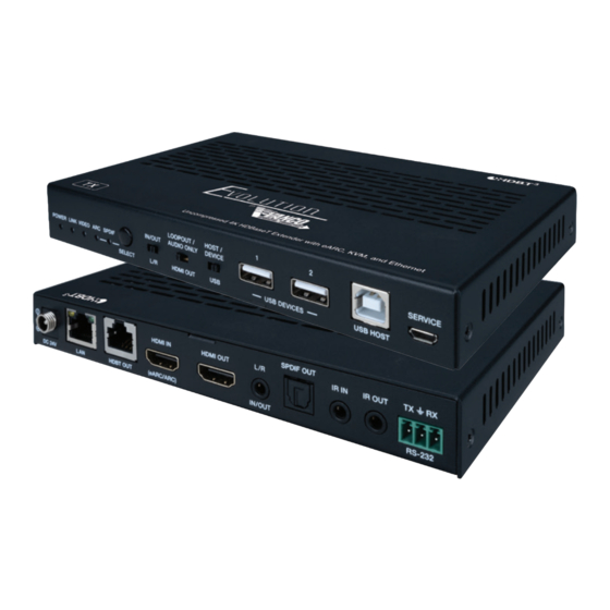
Page 6: Panel Descriptions
PANEL DESCRIPTIONS Transmitting Unit 1. Power LED: Illuminates when the unit is powered on 2. Link LED: Light on: Transmitter and Receiver are connected and communicating Light flashing: Transmitter and Receiver are in Low Power Mode (check cabling, home-run cabling should be utilized with no coupling points) Light off: No connection between Transmitter and Receiver 3. - Page 7 Host/Device USB Switch The USB pass-through on this unit is bi-directional, however is not simultaneous, which means one unit must be set to “HOST”, and the other to “DEVICE” Switch to left (HOST), the USB host port, connects to a PC, security NVR, etc.; the USB ports on the Receiving unit will be active to connect a keyboard/mouse Switch to right (DEVICE), the USB DEVICE mode is enabled to connect a keyboard/mouse, the Receiving unit must be set to “HOST”...
- Page 8 PANEL DESCRIPTIONS Receiving Unit 1. Power LED: Illuminates when the unit is powered on 2. Link LED: Light on: Transmitter and Receiver are connected and communicating Light flashing: Transmitter and Receiver are in Low Power Mode (check cabling, home-run cabling should be utilized with no coupling points) Light off: No connection between Transmitter and Receiver 3.
- Page 9 USB DEVICES: USB device ports to connect to a keyboard/mouse USB HOST: USB extension host port, connected to smart or touch screen display 10. SERVICE: Firmware update port 11. DC 24V: DC 24V/1A power supply input port. Note that the extender supports PoH function, allowing for either Transmitter or Receiver to be powered without the use of a power supply 12.
-
Page 10: Connect And Operate
CONNECT AND OPERATE The EVEXHDB3 has MANY different ways it can be setup and used for a variety of different jobs. Here are different scenarios of how it can be setup. The Extender can switch to ARC/SPDIF mode by pressing the SELECT button on the front panel of both transmitter and receiver. - Page 11 HDMI Loop-Out - AUDIO ONLY This setup allows for audio to be received into the receiver, and extracted from the HDMI OUTPUT of the transmitter. This is often referred to as the ARC backup plan as it allows audio from a display or smart TV to be routed back to the transmitter, then extracted for use with an AVR or distributed audio system in a similar way to ARC.
-
Page 12: Spdif Audio
SPDIF Audio This setup allows audio to be extracted from the SPDIF port on the transmitter. Note: When using SPDIF for audio, only audio formats up to 5.1CH can be passed. Set the Extender (either the Transmitter or Receiver, the other end will update to this mode) to SPDIF Mode Switch the LOOP OUT/ AUDIO ONLY switch to right, the HDMI OUT port of the transmitter is set to AUDIO ONLY... - Page 13 HDMI Audio and Video Loop-Out Utilizing the HDMI loop-out on the Transmitter to output video and audio from source (HDMI IN on TX): Set the Extender to SPDIF Mode Then switch the LOOP OUT/ AUDIO ONLY switch to left, the HDMI OUT port of the transmitter is set to LOOP OUT, which will output both video and audio from the source (HDMI IN on the Transmitting unit) 800.626.6445...
- Page 14 Audio Embedding and De-emedding The Transmitter supports audio embedding and de-embedding (extraction). The L/R IN/OUT port can be used for audio embedding or de-embedding through the L/R IN/OUT switch TX Audio Embedding When the L/R IN/OUT switch is switched to the left, the audio from external audio device will be embedded to the L/R IN/OUT port.
- Page 15 USB Mode Applications The Extender supports USB 2.0 transmission to control a components such as keyboard, mouse, touchscreen display, as well as with USB microphones, and video cameras as well. Note: While the extender can pass USB signals either way (bi-directional), it cannot pass the USB signals both ways simultaneously, one side needs to be set to “HOST”, while the other side needs to be set to “DEVICE”.
-
Page 16: Ir Pass-Through
IR PASS-THROUGH IR PASS-THROUGH The bi-directional IR system allows you to control the source that is connected to the extender unit, from the display; or the display from the source, not simultaneously. There are two important things to note when setting up the IR system: 1. -
Page 17: Limited Warranty
If repairs are needed during the warranty period the purchaser will be required to provide a sales receipt/sales invoice or other acceptable proof of purchase to the seller of this equipment. The seller will then contact Vanco regarding warranty repair or replacement. -
Page 18: Technical Support
TECHNICAL SUPPORT In case of problems, please contact Vanco Technical Support by dialing 1-800-626-6445. You can also email technical support issues to techsupport@vanco1.com. When calling, please have the Model Number, Serial Number (affixed to the bottom of the unit) and Invoice available for reference during the call. - Page 19 800.626.6445...
- Page 20 ® Vanco International 506 Kingsland Drive Batavia, Illinois 60510 call: 800.626.6445 fax: 630.879.9189 visit: www.vanco1.com...
Need help?
Do you have a question about the Evolution EVEXHDB3 and is the answer not in the manual?
Questions and answers