Advertisement
Quick Links
Advertisement

Related Manuals for TRONXY X5SA-400-2E


Summary of Contents for TRONXY X5SA-400-2E
- Page 1 X5SA-2E Installation Manual...
- Page 2 Thank you for choosing TRONXY products! We will serve you whole heartedly! Please read the instruction carefully Please visit tronxy.cn for more information After- sale service:support@tronxy.com TEL:+86-755-89968500 Relevant information is stored in SD card,please check...
- Page 3 Pay attention Please read this instruction carefully and follow the safety instruction. When the 3D printer is working, it will produce high temperature.Do not touch working parts or extruder directly.After printing, the working part may still be in the high temperature state.Please wait patiently for the working parts and the print model to cool down before removing the model from the print platform.
-
Page 4: Table Of Contents
Catalogue 1. Machine parameter ………………………………………1 2. Introduction to machine structure …………………2 3. Packing list ……………………………………………………3 4. Installation instructions …………………………………4 5. Interface operation and printing …………………17 6. Slice software ………………………………………………21 7. Fault cause analysis ………………………………………24... -
Page 5: Machine Parameter
Temperature parameters 8 ℃ - 40 ℃ Environmental temp: Max260 ℃ Nozzle temp: Heat bed temp: support Software Slice software: Cura Tronxy Input format: .STL .OBJ Output format: GCode Connection: TF card, USB cable(Suitable for skilled users) Power supply Power input: 110V/220V AC, 50/60Hz Power output :... -
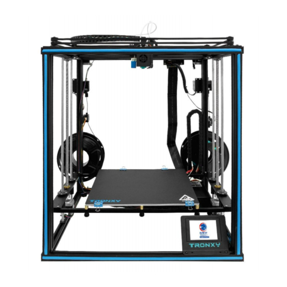
Page 6: Introduction To Machine Structure
2. Introduction to machine structure ⑦ ⑥ ⑧ ⑤ ⑨ ④ ⑩ ③ ⑪ ② ① ⑫ ⑬ ㉑ ⑭ ㉒ ㉓ ⑳ ⑱ ⑲ ⑯ ⑰ ⑮ 1.Touch screen 2.Z1motor 3.Heatbed 6.X motor 4.Y axis switch 5.Y right slider 12.Z2motor 7.extruder head 9.Y left slider 10.lead screw 11. -
Page 7: Packing List
3. Packing list 2020 aluminum polished rod 2040 aluminum profile footlock/beam L eft retrn board 528MM 4pcs profile 530mm 554mm 1pcs lead screws 2pcs Right retrn board 530mm 4pcs 453MM 2pcs 4pcs 600mm 4pcs left /right belt Titan extruder print head X/Y axis motors Zaxis motor parts 2pcs... -
Page 8: Installation Instructions
4. Installation instructions Step 1:base frame assembly Assembly material specification and quantity : aluminum 1 aluminum 2 aluminum 3 foot pad Φ20*12 20*20*600 4pcs 20*20*530 2pcs 20*40*530 4pcs 4pcs screws RM4*8 gasket M4 boat nuts M4 scews RM5*25 4pcs 4pcs 4pcs 12pcs 2-aluminum 1... - Page 9 Step 2: Sliding plate assembly Assembly material specification and quantity : base frame aluminum 2 left sliding parts right sliding screws RM5*25 1pcs 20*20*530 2pcs 1pcs parts 1pcs 4pcs Screw RM5*25 do not lock the Y-axis aluminum 1.Take out thealuminum 2 and put it profile 2 to facilitate subsequent adjustment into the left and right sliding parts respectively, as shown in the figure.
- Page 10 Step 3:Print head assembly Assembly material specification and quantity : Print head parts basic frame aluminum 4 drag chain screws RM4*20 1pcs 1pcs 20*20*554 1pcs plate 1pcs 4pcs As shown in Figure 1, the pulley on the print head penetrates into the sliding slider of aluminum profile 4 smoothly without any gap shaking print head...
- Page 11 Step 4:XY axis motors and wheels assembly Assembly material specification and quantity : basic frame parts right wheel parts left wheel parts X motor Y motor 1pcs 1pcs 1pcs 1pcs 1pcs 1. Lock and fix the assembled parts in the position as shown in the figure Assembly tips for M4 ship nut: first align the M4 nut with the aluminum...
- Page 12 Step 5:Belts assembly Assembly material specification and quantity : basic frame Belt Ties 1pcs 2pcs Note: Synchronization wheels on X, Y axis motors X motor Height should be adjusted by itself. Be sure to install the belt Each belt is on the same planeUp. Belt tying diagram Y motor 1.As shown in the figure, after adjusting the distance between the motor...
- Page 13 Step 6:Linear bearing assembly Assembly material specification and quantity : beams Linear bearing copper linear screws RM3*12 bearing base 2pcs 4pcs bearing 24pcs parts 2pcs 2pcs screws RM4*8 boat nuts M4 Zaxis motor parts 8pcs 8pcs 2pcs 12-M3*12 Bearing pedestal installation: 2 sets in total bearing base parts 2-M4*8 bearing base parts...
- Page 14 Step 7:Z axis parts assembly Assembly material specification and quantity : basic frame Z axis motor parts foot lock parts bearing base parts polish rod 1pcs 2pcs 2pcs 2pcs Φ8*528 4pcs Dφ5*dφ4.2*1 lead screwT8*453 screws RM4*20 screws RM4*8 Shim 2pcs 8pcs 4pcs bearing base parts...
- Page 15 Step 8:Controller box assembly Assembly material specification and quantity : basic frame Z axis motor parts screws RM4*6 boat nuts M4 1pcs 2pcs 2pcs 1pcs Separate the screen from the host and Fix the boat nut on the main box to the Fix the M4 boat nut on the bottom rack as shown bottom shelf with the locking L corner code, as shown in the figure...
- Page 16 Step 9:Print plate assembly Assembly material specification and quantity : basic frame heat bed parts beams plastic nuts M3 screws RM3*16 1pcs 1pcs 2pcs 6pcs 2pcs spring nuts M3 screws KM3*30 screws RM4*12 drag chain parts 6pcs 6pcs 6pcs 8pcs 1pcs Place the left and right horizontal plates on the same plane, and lock the hot bed assembly on the horizontal...
- Page 17 Step 10:Feeding motor assembly Assembly material specification and quantity : screw RM4*6 boat nuts M4 basic frame filament run out Titan extruder 8pcs 12pcs 1pcs detection parts 2pcs 2pcs screw M4*12 material rack 4pcs 2pcs Assemble Titan extruder to filament runout detection parts Titan extruder filament run out detection parts...
- Page 18 Step 11:Assembly of limit switch and end cover Assembly material specification and quantity : Y axis switch lpcs boat nuts M4 screw PM4*8 printer end cap 4pcs 4pcs 1pcs 8pcs Assemble the parts according to the drawing 8-end cap...
- Page 19 Step 12:Black sticker and seal assembly Assembly material specification and quantity : printer clips seal 1pcs 4-clips seal...
- Page 20 controller box Step 13:Wiring X-motor Y axis switch E motor filament break detection heatbed heating heat bed controller Z2 motor Z1motor heat bed Z2 motor Y motor E2 motor Y-motor E motor E2 motor X motor filament break detection filament run out detection Z1 motor Y axis switch...
-
Page 21: Interface Operation And Printing
Interface operation and printing... - Page 22 Print test: ,start print。 Click →“Testing file”→ If the first layer is not sticky, the nozzle is on the high side and the platform can be raised appropriately; If the nozzle has a small amount of thread, the nozzle is on the low side and the platform can be appropriately lowered.
- Page 23 Precautions for double extrusion printing operation: Enter the manual menu, switch to E1, and set the moving length to 10 mm. Click to enter consumables Nozzle with consumable extrusion,Click return , the return length is 43mm. Click E1 in the lower left corner to switch to E2, and the moving length is set to 10 mm.
- Page 24 Manual leveling: Click the four points of ABCD in the figure below, the print head will move to the corresponding position, and then adjust the leveling nut M, so that the interval between the nozzle and the platform is a piece of A4 paper. After adjusting the four points in turn, it needs to be verified again.
-
Page 25: Slice Software
6.Slice software 1. Installation Find out slice software in SD card“TronxyInstall.exe ”double click, Then follow these steps to complete the installation. - Page 26 2. How to use slice software ① 、Type setting: follow the steps below to complete the setting. ① ② ③ ④ ⑤ ⑥...
- Page 27 ② 、Parameter setting:(The following figure gives the reference value, according to their own needs can be modified) Some parameters are set for reference: Layer thickness : 0.1-0.4mm : PLA - 200 ℃ ABS - 240 ℃ Print temp Heatbed temp : PLA - 50℃ ABS - 80 ℃...
-
Page 28: Fault Cause Analysis
7.Fault cause 1. Machine cannot start ? 1)Check the power line and other wires connect correct or not. 2)Check whether the supply voltage matches the local standard. 3)Check whether the screen or power supply is damaged and replace in time. 4)Check the wires if damage or breakage. - Page 29 1)Heating the hot bed to 50-70 ℃, and after cooling to try again, or use the shovel. 2) It is recommended to buy TRONXY magnetic stickers. 6. Can't heat it up? 1)Check the heating rod and thermistor for poor contact or damage.
- Page 30 9. Model dislocation and fault 1)Nozzle feeding not smoothly, please clean the nozzle or replace the nozzle 2)Check that if the printing speed is too fast 3)The quality of filaments is poor, please replace with new filaments 10. Abnormal sound and vibration of filaments feeding motor 1)Please check whether the nozzle is blocked 2)The nozzle feeding is not smooth, please clean the nozzle...
Need help?
Do you have a question about the X5SA-400-2E and is the answer not in the manual?
Questions and answers