Advertisement
Advertisement

Related Manuals for TRONXY X5SA-500-2E


Summary of Contents for TRONXY X5SA-500-2E
- Page 2 Thank you for choosing TRONXY products! We will serve you whole heartedly! Please read the instruction carefully Please visit tronxy.com for more information TEL:+86-755-89968500 Relevant information is stored in SD card,please check...
- Page 3 عب : البيعsupport@tronxy.com د 판매 후 서비스 : support@tronxy.com Servicio postventa: support@tronxy.com Serviço pós-venda: support@tronxy.com After- sale service:support@tronxy.com アフターサービス:support@tronxy.com Service nach dem Verkauf: support@tronxy.com Послепродажное обслуживание: support@tronxy.com Aftersale contact Facebook QR Code TRONXY QR Code...
- Page 4 Pay attention Please read this instruction carefully and follow the safety instruction. When the 3D printer is working, it will produce high temperature.Do not touch working parts or extruder directly.After printing, the working part may still be in the high temperature state.Please wait patiently for the working parts and the print model to cool down before removing the model from the print platform.
-
Page 5: Table Of Contents
Catalogue 1. Machine parameter ………………………………………1 2. Introduction to machine structure …………………2 3. Packing list ……………………………………………………3 4. Installation instructions …………………………………4 5. Interface operation and printing …………………21 6. Slice software ………………………………………………23 7. Fault cause analysis ………………………………………26... -
Page 6: Machine Parameter
1. Machine parameter Print parameters Print principle: FDM (Fused deposition molding) Print size: 500× 500×600 (mm3) Print accuracy: 0.1-0.4 mm X/Y0.00625mm , Z 0.0125mm Positioning accuracy: Nozzle quantity: Nozzle size: 0.4 mm Print speed: 20~100mm/s (suggest 60mm/s) Moving speed: 100mm/s Filament: PLA, TPU, ABS, wood, etc. -
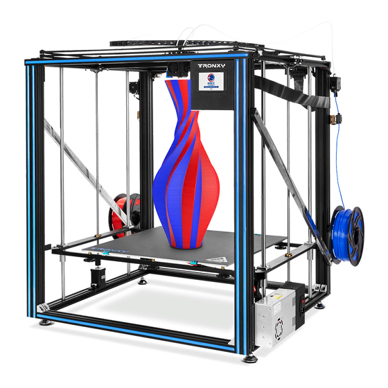
Page 7: Introduction To Machine Structure
2. Introduction to machine structure ⑧ ⑦ ⑨ ⑩ ⑥ ⑤ ⑪ ④ ⑫ ③ ⑬ ② ⑭ ① ⑮ ⑱ ⑳ ⑲ ㉑ ⑰ ⑯ 1.Power Supply 4.Y axis switch 2.Stainless steel pipe 3.Heatbed 5.Y- right skateboard 6.Y- Aluminum profile 7.Xmotor 8.Ymotor 9. -
Page 8: Packing List
3. Packing list 2040aluminum 2020aluminum 2040aluminum Stainless steel profile profile 040aluminum profile profile pole 2PCS 630mm 2PCS 740mm 2PCS 780mm 4PCS 670mm 2PCS 660mm 2PCS 654mm 1pcs polished rod beams/footlock left and right 760MM 4PCS left /right belt pulley X/Y axis motors 2pcs sliding parts lead screws... -
Page 9: Installation Instructions
4. Installation instructions Step 1:base frame assembly Assembly material specification and quantity: aluminum1 aluminum2 aluminum3 Corner code 40*40*780 4PCS 40*20*660 2PCS 40*20*630 2PCS 20PCS screws M4*8 gasket M4 boat nuts M4 screws M5*45 40PCS 40PCS 40PCS 8PCS M6 threaded hole M6 threaded hole 2-aluminum1 2-aluminum1... - Page 10 Step 2: Sliding plate assembly Assembly material specification and quantity: Aluminum5 base screwsM6*25 aluminum4 left sliding plate right sliding plate 20*40*670 frame 20*20*740 2PCS component 1pcs component 1pcs 16PCS 2pcs 1pcs The screw M6*25 is slightly locked on Aluminum5 to facilitate subsequent adjustment. 2aluminum 4 8-M6*25 Note: The installation position of Aluminum Profile...
- Page 11 Step 3: Sliding plate assembly Assembly material specification and quantity: Aluminum6 Print head parts drag chain plate screws 20*20*654 basic frame 1pcs 1pcs 1pcs M4*20 6PCS 1pcs As shown in the figure, the pulley on the print head runs through the Aluminum6 and the slide block moves smoothly without any clearance print head pulley...
- Page 12 Step 4:XY axis motors and wheels assembly Assembly material specification and quantity: basic frame parts right wheel left wheel parts X motor Y motor 1pcs parts 1pcs 1pcs 1pcs 1pcs 1. Lock and fix the assembled parts in the position as shown in the figure Assembly tips for M4 ship nut: first align the M4 nut with the aluminum profile slot, put it into the aluminum...
- Page 13 Step 5:Belts assembly Assembly material specification and quantity: basic frame Belt Ties 1pcs 2pcs X motor Belt tying diagram Y motor Location of Print Head Band Left and right wheels 1.As shown in the figure, after adjusting the distance between the motor gear and the belt, lock the 2 rice screws on the gear.
- Page 14 Step 6:Linear bearing assembly Assembly material specification and quantity: copper linear screws M3*8 beams Linear bearing screws M4*12 bearing 8pcs 2pcs 4pcs 16pcs 2pcs 16-M4*12 8-M3*8...
- Page 15 Step 7:Z axis parts assembly Assembly material specification and quantity: basic frame Z axis motor parts foot lock parts bearing base parts polish rod 1pcs 2pcs 2pcs 2pcs Φ8*760 4PCS lead screwT8*665 screws M4*30 screws M4*8 screws M4*25 2PCS 8PCS 4PCS 8PCS polish...
- Page 16 Step 8: feed motor installation Assemble material specification and quantity : mainframe 1pcs feed motor component boat nuts M4 screws PM4*6 2pcs 2pcs 2pcs 1. Assemble the feeding motor components as shown in the picture with 2 PM4*6 screws and boat nut M4. 2.
- Page 17 Step 9: print platform assembly Assemble material specification and quantity: Hot bed (with drag plastic screws boat nuts chain)500*500*3 1pcs nuts M3 PM4*8 mainframe 1pcs beam 2pcs spring 6pcs 2pcs 2pcs 6pcs screws Double nuts M3 PM4*12 limit screws KM3*35 6pcs 8pcs plate 2pcs 8pcs...
- Page 18 Step 10: control box assembly (this step can be installed after wiring) Assemble material specification and quantity: controller box Power Supply mainframe 1pcs 1PCS 1PCS boat nuts...
- Page 19 Step 11: assemble the rack Assemble material specification and quantity: 3d printer 1set boat nuts M4 screws PM4*6 Bracket part 2pcs 2pcs 2PCS 2. Fix the material rack assembly into the 1. Pick 1 piece material rack plate, 2 aluminum profile groove with boat nut, and screwsPM4*6, 2 boat nut M4, assemble as lock the 2 screws PM4*6, as shown in the shown.
- Page 20 Step 12: decorative strip and feeding tube, lattice glass assembly Assemble material specification and quantity: 3d printer 1set Decorative strip 1 l feed tubeΦ4 clip 4pcs Print platform 1pcs sticker 1. Pull the feeding tube into the air nozzle 2. Cut the decorative strip to the appropriate hole of the feeding component, press down the length and press it into the aluminum profile plastic outer ring of the air nozzle, insert...
- Page 21 Step 13: limit switch assembly Assemble material specification and quantity: screws 3d printer Y Switch boat nuts PM4*8 1pcs 1pcs M4 2pcs 2pcs 2. Fix the Y switch assembly in the aluminum 1. Put 2pcs screw PM4*8 through Y switch profile groove with boat nut, as shown in component, then lock with T nut M4, same the figure.
- Page 22 Step 14: assemble the filament run out detector Assemble material specification and quantity: 3d printer detector 1set 1pcs 1. Take the boat nut M4, screw PM4*12, as 2. Fix the switch assembly with boat nut M4 shown in the figure, align with the switch and screw PM4*12 on the aluminum profile at assembly, and screw in the lower end of the...
- Page 23 Step 15: strengthen rods and chains assembly Assemble material specification and quantity: screws screws screws 3d printer strengthen boat nuts Foot cup End cover PM4*16 PM4*12 PA3*10 1pcs rods 2pcs M4 8pcs 4pcs 4PCS 4pcs 4pcs 4pcs 1. Take 1 strengthen rods , 2 boat nuts and 3.Install end cover 2 screws PM4*16, and screw in the stiffener according to the...
- Page 24 Step 16: wiring heatbe heatin heat Power cord motor motor motor motor filament run detection motor motor Y-axis switch line Y axis switch filament break detection Adapter plate Insert a flat cable...
-
Page 25: Interface Operation And Printing
Interface operation and printing Print test: ,start print。 Click →“Testing file”→ If the first layer is not sticky, the nozzle is on the high side and the platform can be raised appropriately; If the nozzle has a small amount of thread, the nozzle is on the low side and the platform can be appropriately lowered. - Page 26 Precautions: Before each zeroing or automatic leveling, the Z axis must be lowered to the position below the photoelectric sensor switch, as shown in the figure below Double limit Photoelectric plate sensor switch The board is in the switch sensing area Auto leveling:...
-
Page 27: Slice Software
6.Slice software 1. Installation Find out slice software in SD card“TronxyInstall.exe ”double click, Then follow these steps to complete the installation. - Page 28 2. How to use slice software ①、Type setting: follow the steps below to complete the setting. ① ② ③ ④ ⑤ ⑥...
- Page 29 ②、Parameter setting:(The following figure gives the reference value, according to their own needs can be modified) Some parameters are set for reference: Layer thickness : 0.1-0.3mm : PLA - 200 ℃ ABS - 240 ℃ Print temp ABS - 80 ℃ Heatbed temp :...
-
Page 30: Fault Cause Analysis
7.Fault cause analysis 1. Machine cannot start ? 1)Check the power line and other wires connect correct or not. 2)Check whether the supply voltage matches the local standard. 3)Check whether the screen or power supply is damaged and replace in time. 4)Check the wires if damage or breakage. - Page 31 1)Heating the hot bed to 50-70 ℃, and after cooling to try again, or use the shovel. 2) It is recommended to buy TRONXY magnetic stickers. 6. Can't heat it up? 1)Check the heating rod and thermistor for poor contact or damage.
Need help?
Do you have a question about the X5SA-500-2E and is the answer not in the manual?
Questions and answers
Принтер: X5SA-500-2E. Произвожу автоматическое выравнивание стола и при помощи Z ofset отрегулировал и запомнил требуемое расстояние между столом и соплом толщиной бумаги около 0,1 мм. При запуске печати принтер игнорирует выше указанное действие и начинает вести сопло над столом на гораздо большем расстоянии и потому не происходит адгезия выдавливаемого пластики со столом.
The TRONXY X5SA-500-2E printer may ignore the Z offset settings and print at a greater distance from the bed due to improper leveling or incorrect Z offset calibration. The manual states that after automatic leveling, if any error value is greater than 0.5, adjustments must be made until all values are below 0.5. Additionally, during Z offset calibration, the nozzle height should be adjusted to the thickness of an A4 paper before resetting the zero position. If these steps are not properly completed, the printer may not register the correct Z offset, leading to poor first-layer adhesion.
This answer is automatically generated
Скажите, на схеме сборки есть механические концевики, а в наборе два оптических. У меня есть механических концевики от других версий Тронкси X5SA, Можно этими концевиками заменить оптические?