Advertisement
Quick Links
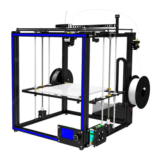
Step 1: assemble the underframe
Assembly material specification and quantity:
Aluminum1 20*20*530
4pcs
boat nutsM4 4pcs
1. Take Aluminum1, 2 pieces, Aluminum2,2 pieces, Aluminum3,4
pieces, assemble them in the direction shown, and fasten them
with 8 screws of PM5*25.
Note: before locking the screws, align the edges of the aluminum
profile vertically.
2. Take the Foot pads, spacer M4, screw PM4*9 and boat nut M4,
assemble them in the order shown, and lock them on the
aluminum profile 1, about 20mm away from the end.
Assembly technique of M4 boat nuts: first, align the M4 nut with
the aluminum profile groove and put it into the aluminum profile
groove. Unscrew with the screwdriver and release the M4 boat nut
to cross the aluminum profile inner groove and then screw it
forward.
Aluminum2 20*20*460
2pcs
1 product assembly
Aluminum3 20*40*530
4pcs
Aluminum1
Aluminum2
Aluminum3
3. Take Aluminum1 2pcs, assemble them in the direction shown,
and screw them with 4 screws of PM5*25.
Note: do not lock the screw tightly to facilitate subsequent
adjustment.
Foot padΦ
screwsPM5*
26*12 4pcs
25 12pcs
screwsPM4*
spacerM4
9 4pcs
4pcs
Aluminum
1
Advertisement

Subscribe to Our Youtube Channel
Related Manuals for TRONXY X5S 2E


Summary of Contents for TRONXY X5S 2E
- Page 1 1 product assembly Step 1: assemble the underframe Assembly material specification and quantity: Aluminum1 20*20*530 Aluminum2 20*20*460 Aluminum3 20*40*530 Foot padΦ screwsPM5* screwsPM4* spacerM4 4pcs 2pcs 4pcs 26*12 4pcs 25 12pcs 9 4pcs 4pcs boat nutsM4 4pcs 1. Take Aluminum1, 2 pieces, Aluminum2,2 pieces, Aluminum3,4 pieces, assemble them in the direction shown, and fasten them with 8 screws of PM5*25.
- Page 2 Step 2: install the sliding plate Assembly material specification and quantity: underframe Aluminum2 20*20*460 screwsPM5* boat nutsM4 screwPM4*8 left sliding plate components right sliding plate 1pcs 1pcs components 1pcs 2pcs 25 4pcs 4个 4件 1. Take Aluminum2 2pcs and insert the left and right components 2.
- Page 3 Step 3: print head installation Assembly material specification and quantity: screws screws Aluminum4 print head boat nutsM4 nuts M3 drag chain screws frame 1pcs 20*20*484 PM3*16 PM4*12 component(incl 4个 4pcs riser 1pcs PM3*8 2pcs drag chain) 1pcs 1pcs 2pcs 2pcs 1.
- Page 4 Step 4: installation of XY motor components and over-wheel installation Assembly material specification and quantity: right over- left over- underframe screwsPM4* Y motor X motor wheel wheel boat nutsM4 screwsPM4* screwsPM3* component motor 2pcs 8 6pcs plate 1pcs plate 1pcs component component 10pcs...
- Page 5 Step 5: assemble the belt Assembly material specification and quantity: frame 1pcs belt 2pcs Tie 4pcs 1. Move the belt through as shown, wrap the motor gear on the rack surface, and determine the belt trend. Press the slide plate against the motor bottom plate and fasten it with the tie belt at the lower end of the sheet metal groove of the print head assembly.Loosen the motor baseplate screw, pull the motor...
- Page 6 Step 6: assemble linear bearing and z-axis motor Assembly material specification and quantity: Z axis motor component beam 2pcs linear bearing 4pcs feed crew nut 2pcs screwPM3*8 24pcs 2pcs screwPM4*9 4pcs bearing block 2pcs screwPM4*12 4pcs gasketM4 4pcs boat nuts 8pcs 1.
- Page 7 Step 7: assemble Z axis components Assembly material specification and quantity: beam Polished rod Lead bearing block screwsPM4* frame 1pcs Z axis motor bracket 2pcs component Φ8*528 screwT8*453 components 20 8pcs 2pcs 2pcs 4pcs 2pcs 1. Take 1 piece of motor bracket of Z axis, insert the polished rod into the acrylic plate hole of the motor bracket, and do not protrude, as shown in the figure.
- Page 8 Step 8: feed motor installation Assembly material specification and quantity: left feed motor right feed motor frame 1pcs screwPM4*12 4pcs boat nutsM4 4pcs component 1pcs component 1pcs 1. Use 2 PM4*12 screws and boat nut M4 to lock the feeding 2.
- Page 9 Step 9: print platform assembly Assembly material specification and quantity: frame 1pcs hotbed 330*330*3 1pcs beam 2pcs plastic nutsM3 6pcs spring 6pcs drag chain drag chain nutsM3 screwPM4*1 screwsPM3* screwKM3*1 screwKB3*8 screwKM3*30 6pcs support baseboard 8pcs 2 8pcs 10 2pcs 0 2pcs 2pcs 1pcs...
- Page 10 Step 10: motherboard assembly Assembly material specification and quantity: screwPM3*4 screwPM4*6 mainframe 1pcs Main components 1pcs The fan cover 1pcs boat nutsM4 3pcs 4pcs 3pcs 1.Take the main board assembly and fan cover plate, place them in 3.Fix the main board assembly with boat nut on the aluminum profile the position shown, and lock them with 4 PM3*4 screws.
- Page 11 Step 11: power supply installation Assembly material specification and quantity: power 30A component screwPM4*9 boat nutsM4 mainframe 1pcs 1pcs 3pcs 3pcs 1. Select the power component and select the voltage of 2. Fix the aluminum profile groove with the boat nut and lock the 3 110V/220V according to the power supply voltage in the screws PM4*9, as shown in the figure.
- Page 12 Step 12: assemble the filament rack Assembly material specification and quantity: rack plate mainframe 1pcs hex screwM8*100 2pcs boat nutsM4 4pcs screwPM4*12 4pcs nutsM8 4pcs 2pcs 1. Take 1 piece of material rack plate, 1 outer hexagon screw and 2 nut M8, assemble the lock as shown.
- Page 13 Step 13: assemble decorative strip and feeding pipe, glass fiber board Assembly material specification and quantity: mainframe 1pcs decorative strip 1roll feeding pipeΦ4 2pcs glass fiber board 1pcs clamp 4pcs 1. Pull the feeding tube into the air nozzle hole of the feeding 2.
- Page 14 Step 14: limit switch assembly Assembly material specification and quantity: plastic mainframe Switch(incl switch base screwPM3*4 screwPB2*1 boat nutsM4 screw nutsM3 1pcs wiring) 2pcs 1pcs 5 1pcs 0 4pcs 2pcs PM4*9 2pcs 1pcs 1. Take 1 piece of switch seat and 2 pieces of switch, and insert 2 screws PB2*10 into it respectively according to the position shown in the picture, and lock the screws.
- Page 15 Step 15: wiring Assembly material specification and quantity: Switch wire assembly mainframe 1pcs USB cable 1pcs The power cord 1pcs The motor wire 4P*6 2pcs Wrapping tape 1roll HOTBED -DC12V+ FAN1 X-motor E-motor HOTEND Y-motor FAN2 E2-motor X STOP Fan 2 Fan 1 X-motor Y-motor...
- Page 16 Wiring diagram of main board...
- Page 17 2 Touch screen operation guide 1. Enter the main screen of the startup, display the system and tools, print three main menus, and click on the three sub- menus, as shown in the figure.Basic functionality for displaying submenus. 2. Click the system menu and enter it into the system submenu, as shown in the figure: click back menu and return to the superior menu.
- Page 18 2.3 click the Chinese location menu to enter Chinese and English.Click back menu to return to the superior menu. 2.4 click factory Settings to ask whether the factory Settings are restored.Click to return to restart and restore the factory Settings. 2.5 click the screen correction, enter the screen correction and click the cross position for correction.Adjust the screen when clicking the menu deviation, save the return.
- Page 19 3. Click the tools menu to enter the machine parameter setting and adjustment. 3.1.1 click the manual menu to enter the manual adjustment mode.Adjust the motor rotation, E extruder feeding/discharging, XYZ shaft motor moving, ICONS 0.01mm, 0.1mm, 1mm,10mm. After clicking, dark color is displayed, such as icon 10mm.
- Page 20 3.3.1 click the icon of loading and unloading consumables to indicate preheating.Remove the consumables to warm up before pulling them out.Click the number box to heat, the temperature is reached, and click the icon to return the material.When installing the consumables, the front end of the consumables shall be stroked straight into the hole of the feeder, and then protruded.As shown in the figure, pass the consumables through the feeder hole, reach the consumables, and insert the consumables into the bottom of the extrusion head.Click the icon to send the material...
- Page 21 3.4 leveling menu and leveling function, click the icon to enter manual leveling.First, tighten the six adjusting nuts of the printing platform, compress the spring in the shortest position, click the icon , and the printing platform move up. When the Z axis switch stops, adjust the position of the switch adjusting screw/nut, make the nozzle of the extrusion head about 2-3mm away from the moving platform, and lock the switch adjusting screw/nut.Click screen X the extruder head move to the set position, then loosen the adjusting nut of the hot bed and fine-tune the platform to make the distance between the platform and the nozzle to an A4 paper thickness gap size.
- Page 22 3.7 click the Z offset icon to enter the Z axis position adjustment.The function of automatic leveling is effective.This function is not available on this machine. 4. click the print icon to enter the print.The screen displays the files in the machine memory card.Click the arrow to scroll up and down.Click the folder, open the folder, and display the folder contents.
- Page 23 4.1.1 click the icon to stop printing and ask whether to replace the consumables.To replace the consumables, click yes to replace the consumables in step 3.3 and return to continue printing.Click no and go back to print. 4.1.2 click the icon to stop printing, and the machine asks whether it is saved or not.
- Page 24 5. Power failure resume to print: when the machine is printing, the machine will automatically save the current status parameters. When the machine is restarted, the screen will show that the last time it was hit was interrupted.The option is to print from the breakpoint.Select no or cancel, and the parameters are cleared.
- Page 25 3. FAQ 1.Nozzle plugging material: will the print head heated to above 180 ℃, and then use the 0.4 mm (default needle dredge nozzle, until manual feeding normal out of filaments. 2.Pipe plugging material: the printing head is a straight-through pipe. If the feeding pipe is not inserted in it is easy to cause the pipe blocking material.
Need help?
Do you have a question about the X5S 2E and is the answer not in the manual?
Questions and answers