Table of Contents
Advertisement
Advertisement
Table of Contents

Related Manuals for TRONXY X1


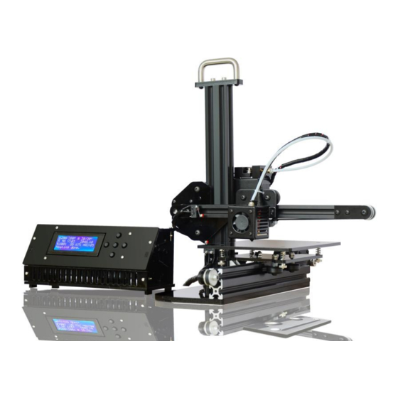
Summary of Contents for TRONXY X1
- Page 3 Step 1 Assemble Base Frame Parts: 2040 Aluminium profile 250mm – 1pcs Base Plate – 1pcs M4-8mm screw – 3pcs M4 T-Nut – 3pcs Put the aluminium profile on the base plate, secure them with 3pcs M4-10mm screws & T-Nut...
- Page 4 Step 2 Assemble Base Frame Parts: 2020 Aluminium profile 70mm – 1pcs Corner bracket – 2pcs M4-8mm screw – 5pcs M4 T-Nut – 5pcs Put the ‘2020 aluminium profile 70mm’ on the base plate, secure them with 1pcs M4-8mm screws &...
- Page 5 Step 3 Install Z Slide rail Parts: 2040 Aluminium profile 310mm – 1pcs Corner bracket – 1pcs M5-10mm screw -2pcs M5-40mm screw – 1pcs M4-8mm screw – 2pcs M4 T-Nut – 2pcs Place ‘2040 aluminium profile 310mm’ on the base plate , secure them with 2pcs M5-10mm screws.
- Page 6 Step 4 Fix the Z slide rail Parts: L-shape Acrylic block – 1pcs M4-8mm screw – 4pcs M4 T-Nut – 4pcs Place 1pcs L-shape acrylic block on the aluminium profile, secure them with 4pcs M4-8mm screws & T-Nut...
- Page 7 Step 5 Assemble Y axis Motor Parts: 42 stepper motor – 1pcs GT2-16 Pulley (with grub screw in it)– 1pcs Limit switch – 1pcs Y motor mount (Acrylic) – 1pcs M3-8mm screws – 4pcs M4-8mm screw – 3pcs M4 T-Nut - 3pcs M2-10mm screw –...
- Page 8 Step 6 Assemble Bed Frame Parts: Bed frame (acrylic) – 1pcs Wheel – 3pcs Plastic pillar – 3pcs M5-30mm- 3pcs M5 nut – 3pcs GT2 Timing belt – 1pcs Zip-ties – 1pcs Secure the wheels in place using M5-30mm screws and nuts ,using plastic pillar between wheel and bed frame.
- Page 9 Step 7 Assemble Y-axis Belt Pulley Parts: Y Pulley mount (acrylic) – 1pcs Belt pulley – 1pcs M5-25mm screw – 1pcs M5 Nut – 2pcs M6 washer – 2pcs M5 washer – 2pcs M4-8mm screw – 3pcs M4 T-Nut - 3pcs ...
- Page 10 Step 8 Install Y axis Timing Belt Parts: Zip-ties – 1pcs Run the other end of timing belt along the aluminium profile, through the Y-GT2-16 Pulley and Belt pulley . Then tighten it to the bed frame using zip-ties as shown in the picture .
- Page 11 Step 9 Assemble Z Carriage Parts: 2020 Aluminium profile 285mm – 1pcs X-motor mount (acrylic) – 1pcs Extruded bracket – 1pcs Brass nut – 1pcs Plastic pillar – 6pcs Wheel – 3pcs M5-40mm screw – 3pcs M5 Locknut – 3pcs M3-8mm screw –...
- Page 12 Step 10 Install Z carriage Parts: 42 stepper motor – 1pcs GT2-16 Pulley (with grub screw in it)– 1pcs M3-8mm screws – 4pcs Carefully insert the X-axis assembly to the Z slide rail Insert the GT2-16 pulley to the motor shaft, tighten the grub screw in the pulley, then place the X stepper motor to the motor mount, secure them with 4pcs M3-8mm screws .
- Page 13 Step 11 Insert Extruder Assembly Parts: Extruder assembly – 1pcs Carefully insert the extruder assembly to the X slide rail.
- Page 14 Step 12 Assemble X axis Endstop & Pulley Parts: Belt pulley – 1pcs Limit switch – 1pcs X Pulley mount (acrylic) – 1pcs X endstop mount (acrylic) – 1pcs M5-25mm screw – 1pcs M5 Nut – 1pcs M4-8mm screw – 4pcs M5 Locknut –...
- Page 15 Step 13 Install X axis Timing Belt Parts: GT2 Timing belt – 1pcs Zip-ties – 2pcs Tighten one end of the timing belt to the belt hole using a zip-ties which back of the extruder Run the other end of timing belt along the aluminium profile, through the X-GT2-16 Pulley and Belt pulley .
- Page 16 Step 14 Assemble Z motor Parts: 42 Stepper motor – 1pcs Z-motor seat – 1pcs Coupling (with grub screw in it) – 1pcs Threaded rod 260mm – 1pcs M3-8mm screw – 4pcs M4-12mm screw – 2pcs M4 T-Nut – 2pcs ...
- Page 17 Step 15 Install Filament Feeder Parts: 42 Stepper motor – 1pcs Feeding gear (with grub screw in it)– 1pcs Extrution clip - 1pcs Extrution seat – 1pcs M3-22mm – 2pcs M3-16mm – 1pcs M5-10mm Hex screw – 1pcs Spring – 1pcs ...
- Page 18 Step 16 Install handle Parts: Handle – 1pcs Handle seat (Acrylic) – 1pcs M5-10mm screw – 2pcs M4-12mm screw – 2pcs Put the handle seat on the top of Z slide rail, secure them with 2pcs M5-10mm screws . ...
- Page 19 Step 17 Install Z endstop Parts: Limit switch – 1pcs Z endstop mount – 1pcs M4-8mm screw – 1pcs M4 T-Nut – 1pcs M2-10mm screw – 2pcs M2 Nut – 2pcs Secure the limit switch to Z endstop mount using 2pcs M2-10mm screws and nuts.
- Page 20 Step 18 Assemble Print bed Parts: Bed plate – 1pcs M3-30mm screw – 4pcs Thumb nut – 4pcs Spring – 4pcs Place the Bed plate on the bed frame use 4pcs springs between them, and then through 4pcs M3-30mm screws, then top 4pcs thumb nuts under the bed frame.
- Page 21 Step 19 Install Teflon hose Parts: Teflon hose – 1pcs Connector – 1pcs Install a connector to the filament feeder , and then insert a teflon hose between feeder and extruder .
- Page 22 Step 20-1 Assemble Electronic Box Parts: Electronic box bottom plate (acrylic) – 1pcs Electronic box side plate – 2pcs Mainboard– 1pcs M3-20mm screws – 6pcs M3 nuts – 6pcs Plastic pillar – 4pcs Place the mainboard on the bottom plate using M3-20mm and nuts , insert the plactic pillar between them.
- Page 23 Step 20-2 Assemble Electronic Box Parts: Electronic box front plate – 1pcs LCD display assembly – 1pcs M3-20mm screws – 4pcs M3 nuts – 4pcs Assemble the front plate using M3-20mm screws and M3 nuts. Place the LCD display assembly to the box , using 2pcs M3-20mm screws and nuts.
- Page 24 Step 20-3 Assemble Electronic Box Parts: Electronic box Back plate (left) – 1pcs DC power jack – 1pcs M3-20mm screws – 1pcs M3 nuts – 1pcs Assemble the back plate to the bottom plate as picture , secure them using M3-20mm screw&nut. ...
- Page 25 Step 20-4 Assemble Electronic Box Parts: Electronic box top plate – 1pcs M3-20mm screws – 3pcs M3 nuts – 3pcs Cover the top plate using M3-20mm screws and M3 nuts.
- Page 26 Step 23 Control Board Wiring Diagram Parts: Mainboard – 1pcs DC power jack The method of connecting wire is as picture There is only 1pcs cooler fan , please connect to ‘CFAN’ on board There do not have heatbed and the thermistor , so there's no connection on ‘Hotbed’...
Need help?
Do you have a question about the X1 and is the answer not in the manual?
Questions and answers