
Related Manuals for TRONXY X5


Summary of Contents for TRONXY X5
- Page 2 Step 1 Assemble Base Frame Parts: 2020 Aluminium profile 355mm – 2pcs 2020 Aluminium profile 380mm – 2pcs 2020 Aluminium profile 500mm – 4pcs Acrylic corner cushion – 4pcs M4-10mm screw – 8pcs M4 T-Nut – 8pcs M5-25mm screws – 4pcs...
- Page 3 Step 2 Assemble Top Frame Parts: 2020 Aluminium profile 355mm – 2pcs 2020 Aluminium profile 380mm – 2pcs Corner bracket –8pcs M4-8mm screws –16pcs M4 T-Nut –16pcs M5-25mm screws – 4pcs...
- Page 4 Step 3 Assemble Z axis Parts: 1: Y axis motor – 1pcs Y axis motor holder (acrylic) – 1pcs Pulley (with grub screw in it) – 1pcs M3-45mm screws – 4pcs M4-10mm screws –2pcs M4 T-Nut –2pcs 2: Z endstop – 1pcs Z endstop holder –...
- Page 5 Step 4 Assemble KP08 Bearings Parts: KP08 Bearing – 4pcs M4-8mm screws –8pcs M4 T-Nut –8pcs...
- Page 6 Step 5 Assemble SK8 support shaft Parts: SK8 support shaft – 4pcs M4-8mm screws –8pcs M4 T-Nut –8pcs...
- Page 7 Step 6 Assemble sliding rods Parts: Sliding rod 420mm – 2pcs Pulley (with grub screw in it) – 5pcs Closed belt – 1pcs...
- Page 8 Step 7 Assemble X-pulley&motor mount Parts: Sliding rod 395mm -2pcs LM8UU linear bearing – 8pcs X-Pulley mount – 1pcs X-motor mount – 1pcs Y-endstop – 1pcs Y-endstop mount – 1pcs M2-10mm – 2pcs M3-16mm – 1pcs M3 nut – 1pcs...
- Page 9 Step 8 Assemble X axis Parts: ① Belt pulley – 1pcs M5-32mm screw – 1pcs ① M6 washer – 3pcs ③ M5 washer – 2pcs M5 nut – 1pcs ② X endstop – 1pcs X endstop holder ( acrylic) – 1pcs M2-10mm screw –...
- Page 10 Step 9 Assemble heat bed Parts: Timing belt – 1pcs Zip-ties – 2pcs Tighten one end of the timing belt to the belt hole which is on the extruder using a zip-ties . Run the other end of timing belt to the X-Motor- Pulley and Belt pulley .
- Page 11 Step 10 Assemble timing belt Parts: Timing belt – 2pcs Belt clip – 4pcs M3-10mm screws – 8pcs Tighten one end of the timing belt using belt clip and M3-10mm screws , the other end through pulley from left and right side , the tighten it on the pulley mount , as picture ...
- Page 12 Step 11 Assemble Base Frame Parts: Bed holder (aluminium) – 2pcs Heat bed – 1pcs M3-35mm – 4pcs Springs – 4pcs Wing nut – 4pcs M4-10mm – 4pcs...
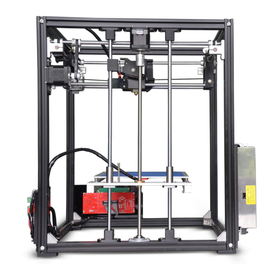
- Page 13 Step 12 Assemble Power supply & Mainboard Parts: ① Power supply – 1pcs Power supply holder (acrylic) – 1pcs M3-10mm screws – 3pcs M4-12mm screws – 3pcs M4 T-Nut – 3pcs ② Mainboard – 1pcs Mainboard holder (acrylic) – 1pcs M3-20mm screws –...
- Page 14 Step 13 Assemble LCD display Parts: LCD display – 1pcs LCD display holder – 1pcs M3-20mm – 4pcs M3 nuts – 4pcs Plastic pillar – 4pcs Control knob – 1pcs M4-12mm screws – 3pcs M4 T-Nut – 3pcs...
- Page 15 Step 14 Control Board Wiring Diagram The method of connecting wire is as picture !NOTE!: The wires connected to POWER SUPPLY and HETBED must be AWG14 or thicker one. No Connection...
- Page 16 Step 15 AC Power Connector Wiring Diagram Connect Power cable as the picture (Left) Note: There are different voltages in different country. Please select the appropriate voltage by switch before power on. As the picture below.
Need help?
Do you have a question about the X5 and is the answer not in the manual?
Questions and answers