Advertisement
Quick Links
Advertisement

Subscribe to Our Youtube Channel
Related Manuals for TRONXY X5SA


Summary of Contents for TRONXY X5SA
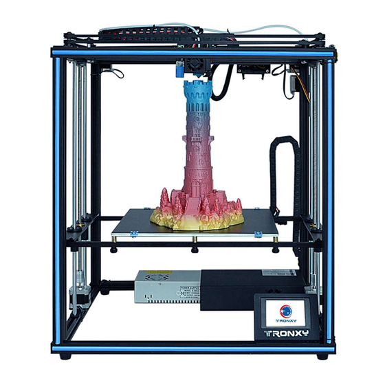
- Page 1 X5SA Installation instructions SHENZHEN TRONXY TECHNOLOG CO.,LTD...
- Page 2 1 Product assembly Step 1. Assemble base frame Assemble parts specifications and quantity: Aluminium profile 1 20*20*530mm Aluminium profile 2 20*20*460mm Aluminium profile 3 20*40*530mm Screw PM5*25 screw PM4*8 Spacer M4 Pad 4pcs 4pcs 2pcs 4pcs 12pcs 4pcs 4pcs T nut M4 4pcs 3.Lock the aluminium profile 1 2pcs with 4pcs screw PM5*25 1.Lock the aluminium profile 1 2pcs, Aluminium profile 2 2pcs, aluminium 3 4pcs together by 8pcs screw PM5*25, same as the illustration.
- Page 3 Step 2:Assemble slider plate Assemble parts specifications and quantity: Screws Alu. profile 2 PM4*8mm M4 T nut Aluminium Frame Slider plate (Left) 1pcs Slider plate (Right) 1pcs 20*20*460mm PM5*25mm screws 4pcs 4pcs 2pcs 4pcs 1, Respectively insert 2pcs PM4*8mm screws to Left and Right slider 3.Put the aluminum 2 components into the end of the aluminum frame 3 plate , lock with M4 T nut , as same as the illustration.
- Page 4 Step 3:Assemble printing head Assemble parts specifications and quantity: Alu. Profile 4 Printing head M4 T-Nut M3 Nut Towline holder PM3*16MM PM3*8MM PM4*12mm Aluminium frame 20*20* 484mm component 2pcs 4pcs 1pcs 2pcs 2pcs 2pcs (with Towline) 1pcs 1pcs 1, Place the towline to the printing heat , secure with 2pcs PM3*8mm screws and M3 Nut Slider plate(Right) Slider plate(Left)
- Page 5 Step 4:Assemble XY axis motor and wheel Assemble parts specifications and quantity: Motor 2pcs(With M4 T-Nut Screws Screws PM4*12 Pulley component Pulley component X Motor base Y Motor base Screws PM3*10 Framework Synchronous (Right) 1pcs (Left) 1pcs plate 1pcs plate 1pcs 8pcs 10pcs...
- Page 6 Step 5:Assemble belt Assemble parts specifications and quantity: Main frame 1pc Belt 2pcs Tie 4pcs 1. Pass the belt through the gear as shown, press the pulley plate 2. Pass the belt through the gear as shown, press the pulley plate against the motor bottom plate, fasten the lower end of the sheet against the motor bottom plate, fasten the lower end of the sheet metal groove of the print head assembly with the tie belt, as...
- Page 7 Step 6:Assemble bearings and Z-axis motor Assemble parts specifications and quantity: Z fixed plate 2pcs Flange bearing 4pcs Copper Nut 2pcs Screws PM3*8 24pcs Z motor component 2pcs Screws PM4*8 8pcs M4 T Nut 8pcs Bearing seat 2pcs 1.Assemble 1pc Z fixed plate , 2pcs bearing seat, 1pc screw nut,12pcs 3.Assemble 1pc Z motor component,2pcs screw PM4*8mm, 2pcs screw PM3*8 together, as the illustration, total need to assemble 2 set.
- Page 8 Step 7:Assemble Z axis component Assemble parts specifications and quantity: Bearing seat Base frame component Z carriage Sliding rod Lead screw Screw PM4*20 Z motor component 2pcs component Φ8*528 4pcs 1pcs 2pcs T8*453 2pcs 8pcs 2pcs 1.Insert the solid end of the Sliding rod to the hole on Z axis motor holder, insert the barrel of the motor holder into the hole,do not let the pole stand out,same as the illustration.Then, put the Z fixed plate component with the pole Φ8*528 together.
- Page 9 Step 8:Assemble feeding motor Assemble parts specifications and quantity: Main framework Screws PM4*12 2pcs M4 T Nut 2pcs Feeding motor component 1pcs 1.Put 2pcs screw PM4 * 12mm through the board holder,then lock them with the T nut M4 screw on the boat nut M4 2.Place the feeding motor component with 2pcs screw PM4*12 and T nut M4 ,same as the illustration Feeding motor component...
- Page 10 Step 9:Assemble printer plateform Assemble parts specifications and quantity: Heatbed (with towline) M3 Wing PM4*8 screw Main framework Metal bar 2pcs Spring 6pcs 330x330mm 1pcs nut 6pcs 2pcs M3 Nut PM4*12 M4 T nut PM3*16 PM3*6 Towline PM3*10 Towline base KM3*30 screw 6pcs 8pcs screw 8pcs...
- Page 11 Step 10:Assemble electronic board and power supply Assemble parts specifications and quantity: Main frame 1pc electronic board and touch-screen component 1pc T nut M4 6pcs Power supply component 1pc Screw PM4*6 3pcs Screw PM4*8 3pcs 3.Take the power supply module, use 3 PM4*8 screws and 3 hull nuts, 1.Use 3 PM4*6 screws and 3 T nuts to tighten according to the and tighten according to the map position.
- Page 12 Step 11:Assemble feeding holder Assemble parts specifications and quantity: Main framework material rack 1pcs T nut M4 2pcs Screw PM4*6 2pcs 1. Pick 1 piece material rack plate, 2 screwsPM4*6, 2 boat nut M4, 2. Fix the material rack assembly into the aluminum profile groove with assemble as shown.
- Page 13 Step 12:Assemble Decorative strip and Feeding tube Assemble parts specifications and quantity: Main framework Aluminium profile seal Feeding tube 1pcs Print platform sticker 1pcs 1.Put the feeding tube into the hole of the Air cock,insert feeding tube, 2.Align the end seal with the end aluminum profile,then press the seal press the outer plastic ring of Air cock,loosen the plastic ring,stuck the into the groove of the aluminum profile,same as illustration.
- Page 14 Step 13:Assemble limit switch Assemble parts specifications and quantity: Limit switch (with wires) M4 T Nut PM4*8 screws Main framework 1pcs 2pcs 2pcs 1. Put 2pcs screw PM4*8 through switch component, then lock with T nut M4, same as illustration 2.Fix switch component in the groove of aluminum profile with 2pcs T nut, then lock 2pcs screw PM4*8,same as the illustration...
- Page 15 Step 14:Assemble Filament alarm Assemble parts specifications and quantity: PM4*12 M4 T Nut Main framework Filament alarm 1pc End cover 8PCS screws 2pcs 2pcs 2.Install the filament alarm device in the position shown in the 1.Put 2pcs screw PM4*12 through cushion plate, then lock with T nut diagram.To press the end cover into two side aluminum end up and M4, same as illustration down.
- Page 16 Step 15:Connecting wire Heat bed FSTOP YSTOP Z2-motor E-motor Z1-motor Printing head The host box BTEMP ZSTOP Printing head HOTBED Power X-Motor Y-Motor Z1-Motor Z2-Motor E-Motor Power Y-Motor X-Motor YSTOP FSTOP...
- Page 17 F STOP X5SA Physical wiring diagram...
- Page 18 2. operation instructions 1. Enter the main screen of the startup, display the system and tools, print three main menus, and click on the three sub-menus, as shown in the figure.Basic functionality for displaying submenus. 2. Click the system menu and enter it into the system submenu, as shown in the figure: click back menu and return to the superior menu. 2.1 click the state and display as shown in the figure: display the machine position state parameters.Click back menu to return to the superior menu.
- Page 19 2.4 click factory Settings to ask whether the factory Settings are restored.Click to return to restart and restore the factory Settings. 2.5 click the screen correction icon to enter the screen correction and click the cross position for correction.Adjust the screen when the menu is off, save it back.
- Page 20 3.2 click the icon of preheating, as shown in the figure, set the heating temperature of the machine extrusion head and the hot bed, heat the icon hot bed and heat the icon extrusion head, and click the icon in the right and left direction to adjust the setting temperature heating.Use the heating function when replacing consumables.
- Page 21 3.4.2 click automatic leveling, the display will return to the superior menu, the machine will move automatically, read the location parameters set and save. 3.4.3 click the manual leveling to enter the menu, please adjust the 4 adjustment nut of heat bed, compress the 4 springs in the shortest possible location, click on the icon circle X icon, stop machine extrusion head moves to set position, please loosen the adjusting nut, release the spring rebound, let between nozzle and hot bed in the thickness of a piece of A4 paper, A4 paper between the nozzle and the platform moving a sense of resistance, but will not cut paper.Please adjust the four points circled in A4 paper thickness.
- Page 22 3.7 click the Z offset icon to enter the Z axis position adjustment.The function of automatic leveling is effective.Select the fine tuning 0.1mm icon, click the icon Z axis to move up, and click the Z axis to move down.Adjust the nozzle and platform to A4 paper thickness. Click the icon set Z to zero and save the setting.This function is automatically leveling Z axis compensation, with leveling function used, leveling simple.
- Page 23 4.2.2 click the icon to stop printing, and the machine asks whether it is saved. Select "save", and the next printing will start from the current state.Select no, machine state reset.Click cancel to continue printing.This function continues for breakpoint.After the model print stops, the stop save state is shut down, and you can continue printing after the next start.Boot prompt last print interrupt, select continue last print.
- Page 24 6. Filament run out detector: when the machine is printing, the machine will automatically save the current status parameters. When the machine is restarted, the screen will show that the last time it was hit was interrupted.The option is to print from the breakpoint.Select no or cancel, and the parameters are cleared.
Need help?
Do you have a question about the X5SA and is the answer not in the manual?
Questions and answers