Advertisement
Quick Links
DESCRIPTION
Demonstration circuit 2787A is a high efficiency, 4 phase,
hybrid converter. It can deliver 12V/100A with the input
voltage from 40V to 60V. The demo board features the
LTC
7821, which uses an architecture that merges a soft-
®
switching switched-capacitor topology with a traditional
step-down converter to provide superior efficiency com-
pared to the traditional switching architectures. It offers
a high efficiency/high density and cost effective solution
for nonisolated intermediate bus applications in power
distribution, datacom and telecom as well as emerging
48V automotive systems.
External MOSFETs switch at a 400kHz fixed frequency for
this demo board and can be programmed from 200kHz to
1.5MHz. The LTC7821's powerful 1Ω N-channel MOSFET
gate drivers maximize efficiency and can drive multiple
MOSFETs in parallel for higher power applications. Due to
its current mode control architecture, multiple LTC7821
devices can be operated in a parallel, multiphase con-
figuration with excellent current sharing and low output
PERFORMANCE SUMMARY
PARAMETER
Input Voltage Range
Output Voltage, V
OUT
Maximum Output Current, I
OUT
Typical Efficiency
Peak Efficiency
Switching Frequency
High Efficiency, Polyphase Hybrid
Specifications are at T
CONDITIONS
V
= 40-60V, I
= 0A to 100A
IN
OUT
V
= 40-60V, V
= 12V
IN
OUT
V
= 48V, V
= 12V, I
= 100A
IN
OUT
OUT
V
= 48V, V
= 12V
IN
OUT
DEMO MANUAL DC2787A
Step Down Converter
voltage ripple to enable much higher power applications.
Other benefits include low EMI emissions due to a soft-
switched front end and reduced MOSFET stress.
The LTC7821 design eliminates the inrush current typically
associated with switched capacitor circuits by prebalancing
the capacitors on start-up. The LTC7821 also monitors sys-
tem voltage, current and temperature for faults, and uses a
sense resistor for overcurrent protection. It stops switch-
ing and pulls the FAULT pin low when a fault condition
occurs. An onboard timer can be set for appropriate restart/
retry times. Additional features include ±1% output voltage
accuracy over temperature, a clock output for multiphase
operation, a power good output signal, short-circuit protec-
tion, monotonic output voltage start-up, optional external
reference, undervoltage lockout and internal charge bal-
ance circuitry. The LTC7821 data sheet must be used in
conjunction with this demo board manual.
Design files for this circuit board are
All registered trademarks and trademarks are the property of their respective owners.
= 25°C
A
LTC7821
available.
MIN
TYP
MAX
UNITS
40
60
12
100
97.6
98
400
V
V
A
%
%
kHz
Rev. 0
1
Advertisement

Related Manuals for Analog Devices 2787A


Summary of Contents for Analog Devices 2787A
- Page 1 High Efficiency, Polyphase Hybrid Step Down Converter DESCRIPTION Demonstration circuit 2787A is a high efficiency, 4 phase, voltage ripple to enable much higher power applications. hybrid converter. It can deliver 12V/100A with the input Other benefits include low EMI emissions due to a soft- voltage from 40V to 60V.
-
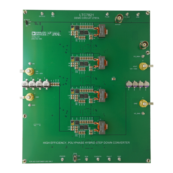
Page 2: Board Photo
DEMO MANUAL DC2787A BOARD PHOTO Figure 1. 4x LTC7821; 100A DC2787A Demo Circuit Rev. 0... -
Page 3: Quick Start Procedure
DEMO MANUAL DC2787A QUICK START PROCEDURE Demonstration circuit 2787A is easy to set up to evaluate 9. After completing all tests, adjust the load to 0A, power the performance of the LTC7821. Refer to Figure 2 for off the input power supply. - Page 4 DEMO MANUAL DC2787A QUICK START PROCEDURE 1mΩ 40V-60V Load (0~100A) Figure 2. Proper Measurement Equipment Setup Figure 3. Measuring Output Voltage Ripple Rev. 0...
- Page 5 DEMO MANUAL DC2787A QUICK START PROCEDURE Efficiency vs Load Current OUTPUT LOAD CURRENT (A) DC2787A F04 Figure 4. Efficiency vs Load Current at V = 12V, f = 400kHz Current Sharing vs Load Current PHASE #1 PHASE #2 PHASE #3 PHASE #4 TOTAL LOAD CURRENT (A) DC2787A F05 Figure 5.
- Page 6 DEMO MANUAL DC2787A QUICK START PROCEDURE (20MHz BW) 100mV/DIV 50A-75A-50A LOAD 20A/DIV 2787A F06 50 /DIV Figure 6. Load Step at V = 48V, V = 12V Figure 7. Thermal performance V = 48V, V = 12V, I = 100A T = 23˚C, No Airflow Figure 8.
-
Page 7: Parts List
DEMO MANUAL DC2787A PARTS LIST ITEM REFERENCE PART DESCRIPTION MANUFACTURER/PART NUMBER Required Circuit Components C1, C6, C68-C70, C74, CAP .,33uF ,ALUM. ELECT.,80V,20%,10x10.2mm SMD, PANASONIC, EEHZA1K330P C153, C154 RADIAL,AEC-Q200 C2, C3, C7, C47, C49, CAP .,2.2uF ,X7R,100V,10%,1210 AVX, 12101C225KAT2A C56, C58, C59, C71-C73, C85-C88, C103-C105, C109, C119, C203, C206-C210... - Page 8 R30, R247 RES.,0.2 OHM,1%,1/2W,2010,SENSE, AEC-Q200 VISHAY, WSL2010R2000FEA SWITCH,SLIDE,DPDT,0.3A,6VDC,PTH C&K, JS202011CQN U1-U4 IC, Hybrid Step-Down Synchronous Controller QFN-32 ANALOG DEVICES, LTC7821EUH#PBF IC, SYNCHRONOUS STEP-DOWN CONVERTER ANALOG DEVICES, LTC3630AEMSE#PBF Additional Demo Board Circuit Components C16, C46, C48, C51, CAP ., OPTION, 0603...
- Page 9 DEMO MANUAL DC2787A PARTS LIST ITEM REFERENCE PART DESCRIPTION MANUFACTURER/PART NUMBER Hardware E1-E6, E8-E15 TEST POINT,TURRET,0.094",MTG. HOLE MILL-MAX, 2501-2-00-80-00-00-07-0 J1-J4 STUD, FASTENER, #10-32 PENNENGINEERING, KFH-032-10ET J5, J6 CONN.,RF , BNC,RCPT JACK,5-PIN,STR, THT,50 Ohms AMPHENOL RF , 112404 J1-J4 RING, LUG, CRIMP ,#10,NON- KEYSTONE, 8205 INSULATED,SOLDERLESS TERMINALS J1-J4...
- Page 10 DEMO MANUAL DC2787A SCHEMATIC DIAGRAM Rev. 0...
-
Page 11: Schematic Diagram
DEMO MANUAL DC2787A SCHEMATIC DIAGRAM Rev. 0... - Page 12 DEMO MANUAL DC2787A SCHEMATIC DIAGRAM Rev. 0...
- Page 13 Devices for its use, nor for any infringements of patents or other rights of third parties that may result from its use. Specifications subject to change without notice. No license is granted by implication or otherwise under any patent or patent rights of Analog Devices.
- Page 14 Board until you have read and agreed to the Agreement. Your use of the Evaluation Board shall signify your acceptance of the Agreement. This Agreement is made by and between you (“Customer”) and Analog Devices, Inc. (“ADI”), with its principal place of business at One Technology Way, Norwood, MA 02062, USA. Subject to the terms and conditions of the Agreement, ADI hereby grants to Customer a free, limited, personal, temporary, non-exclusive, non-sublicensable, non-transferable license to use the Evaluation Board FOR EVALUATION PURPOSES ONLY.
Need help?
Do you have a question about the 2787A and is the answer not in the manual?
Questions and answers