
Related Manuals for Analog Devices EV-SC598-SOM


Summary of Contents for Analog Devices EV-SC598-SOM
- Page 1 ® EV-SC598-SOM Manual Revision 1.0, July 2021 Part Number 82-EV-SC598-SOM-01 Analog Devices, Inc. One Analog Way Wilmington, MA 01887...
- Page 2 Analog Devices, Inc. reserves the right to change this product without prior notice. Information furnished by Ana- log Devices is believed to be accurate and reliable. However, no responsibility is assumed by Analog Devices for its use; nor for any infringement of patents or other rights of third parties which may result from its use. No license is granted by implication or otherwise under the patent rights of Analog Devices, Inc.
-
Page 3: Table Of Contents
Manual Contents ............................1–1 Technical Support ............................1–2 Supported Integrated Circuit ......................... 1–2 Supported Tools............................. 1–3 Product Information ............................1–3 Analog Devices Website..........................1–3 EngineerZone ............................. 1–3 Using the Board Product Overview ............................2–1 Package Contents............................2–3 Default Configuration ........................... 2–3 CrossCore Embedded Studio (CCES) Setup .................... - Page 4 GPIO ( DS1, DS2, DS3 ) ........................3–11 Reset ( DS5 ) ............................3–12 Connectors ..............................3–12 JTAG ( P6 ).............................. 3–13 USB Type C Connector ( P1 )........................3–13 SoM Interface Connection ( J1, J2 and J3 ) ................... 3–14 ® EV-SC598-SOM Manual...
-
Page 5: Preface
(CCES) software development tool chain is required for a full evaluation of this hardware platform. The EV-SC598-SOM can also be used in a limited standalone mode while not plugged into a SoM Carrier such as the EV-SOMCRR-EZKIT or EV-SOMCRR-AUTO . The standalone mode is useful for evaluat- ing the CCES Software Development Tools and benchmarking software algorithms that do not require peripheral I/O. -
Page 6: Technical Support
A companion file in PDF format documenting all of the circuits used on the board is available on the website http://www.analog.com/EV-SC598-SOM Technical Support You can reach Analog Devices technical support in one of the following ways: • Post your questions in the processors and DSP support community at EngineerZone ®... -
Page 7: Supported Tools
If you are a registered user, just log on. Your user name is your e-mail address. EngineerZone EngineerZone is a technical support forum from Analog Devices, Inc. It allows you direct access to ADI technical support engineers. You can search FAQs and technical information to get quick answers to your embedded process- ing and DSP design questions. -
Page 8: Using The Board
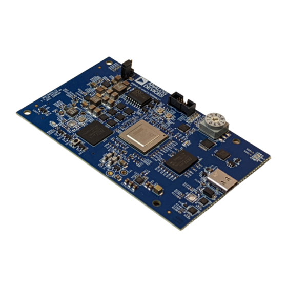
This chapter provides information on the major components and peripherals on the board, along with instructions for installing and setting up the emulation software. Product Overview Below is an image of the EV-SC598-SOM board. Figure 2-1: Board View ® 2–1... - Page 9 Product Overview The board features: • Analog Devices ADSP-SC598 processor • Dual SHARC+ Cores • ARM Cortex A55 Core • 400 ball BGA • 25 MHz oscillator • DDR3 Memory • 256Mx16 bit (4Gbit ) • ISSI IS43TR16256BL-107MBL • 1.35V •...
-
Page 10: Package Contents
Package Contents Your EV-SC598-SOM package contains the following items. • EV-SC598-SOM board Contact the vendor where you purchased your EV-SC598-SOM evaluation board or contact Analog Devices, Inc. if any item is missing. Default Configuration The EV-SC598-SOM board is designed to run as a standalone unit. -
Page 11: Crosscore Embedded Studio (Cces) Setup
ICE-2000 to for debugging. When the EV-SC598-SOM is connected to a carrier board the Debug Agent on the carrier board can be used. To use this Debug Agent, all postions on SW1 (on the carrier board) must be in the ON position. If an emulator, such as the ICE-1000 or ICE-2000, is used instead all postions on SW1 must be in the OFF position. -
Page 12: Power-On-Self Test
The EV-SC598-SOM is powered via USB Type C when the board is in standalone mode. When in this mode the jumper on JP1 should be on Pins 1-2 to select power input from USB Type C . When the EV-SC598-SOM is connected to a carrier board the power is supplied via the carrier board. -
Page 13: Is22Es08G-Jcla - 8Gb Emmc Memory Module
• Refresh Interval: 7.8 µs (8192 cycles/64 ms) Tc= -40°C to 85°C 3.9 µs (8192 cycles/32 ms) Tc= 85°C to 95°C 1.95 µs (8192 cycles/16 ms) Tc= 95°C to 105°C 0.97 µs (8192 cycles/8 ms) Tc= 105°C to 115°C 2–6 ® EV-SC598-SOM Manual... -
Page 14: Lt8636 - 42V, 5A/7A Peak Synchronous Step-Down Silent Switcher With 2.5Μa Quiescent Current
500mV. Other features include output overvoltage protection, short-circuit protection, thermal shutdown, clock synchronization, and up to 100% duty cycle operation for low dropout. The device is available in a low profile 12- lead 2mm × 2mm × 0.74mm LQFN package with exposed pad for low thermal resistance. ® 2–7 EV-SC598-SOM Manual... -
Page 15: Ltc3310S - 5V, 10A Synchronous Step-Down Silent Switcher 2 In 3Mm × 3Mm Lqfn
The STUSB4500 is a USB power delivery controller that addresses sink devices. It implements a proprietary algo- rithm to allow the negotiation of a power delivery contract with a source without MCU support (auto-run mode). PDO profiles are configured in an integrated non-volatile memory. 2–8 ® EV-SC598-SOM Manual... - Page 16 Thanks to its 20 V technology, it implements high voltage fea- tures to protect the CC pins against short-circuits to VBUS up to 22 V and to support high voltage on the VBUS pins directly connected to the VBUS power path up to 28 V. ® 2–9 EV-SC598-SOM Manual...
-
Page 17: Hardware Reference
Hardware Reference 3 Hardware Reference This chapter describes the hardware design of the EV-SC598-SOM . System Architecture The board's configuration is shown in the Block Diagram figure. ® 3–1 EV-SC598-SOM Manual... -
Page 18: Software-Controlled Switches (Softconfig)
C software-control- led switches. The remaining mechanical switches are provided for the boot mode and pushbuttons. Reference any SoftConfig*.c file found in the installation directory for an example of how to set up the SoftConfig feature of 3–2 ® EV-SC598-SOM Manual... -
Page 19: Overview Of Softconfig
EXAMPLE_SIGNAL_B, the Microchip IO expander is used to change ENABLE_A to a logic 1 through software that interfaces with the Microchip. The same procedure for ENABLE_B disconnects EXAMPLE_SIGNAL_C from EXAMPLE_SIGNAL_D. Figure 3-2: Example of Individual FET Switches ® 3–3 EV-SC598-SOM Manual... - Page 20 In this example, the Microchip IO expander is not shown but controls the signal CONTROL_LETTER_NUMBER and allows the user to change the selection through software. 3–4 ® EV-SC598-SOM Manual...
- Page 21 SWE and SWF is OFF. In order to connect the letters instead of the numbers, the user physically changes all switches on SWC and SWD to the OFF position and all switches on SWE and SEF to the ON position. ® 3–5 EV-SC598-SOM Manual...
-
Page 22: Softconfig On The Board
SOM Interface J2 disabled LEDs Enabled Programming SoftConfig Switches On the board, a Microchip MCP23018 devices exist. Each of these devices have the following programming charac- teristics: • Each GPIO register controls eight signals (software switches). 3–6 ® EV-SC598-SOM Manual... - Page 23 FET column. The Component Connected column shows the board IC that is connected if the FET is enabled. The Microchip (U24) is controlling the enable signal of a FET switch. Also note that if a particular functionality of the processor signal is being used, it is in bold font in the Processor Signal column. ® 3–7 EV-SC598-SOM Manual...
- Page 24 EMMC_SOM_EN Enables eMMC signals from U20, U22, MSI Signals High DSP to SOM connectors EMMC_EN Enables eMMC signals from U12, U21, MSI Signals DSP to onboard eMMC memo- ry device NOT USED NOT USED NOT USED NOT USED 3–8 ® EV-SC598-SOM Manual...
-
Page 25: Switches
Default (if applicable) NOT USED NOT USED Switches This section describes operation of the switches. The switch locations are shown in the Switch/Jumper Locations figure. Boot Mode Select Power Selection Reset Button Figure 3-6: Switch/Jumper Locations ® 3–9 EV-SC598-SOM Manual... -
Page 26: Boot Mode Select ( S1 )
Power ( JP1 ) The Power jumper selects the input power source to the EV-SC598-SOM. Pin 1-2 selects power input from the P1 USB Port and Pin 2-3 selects Power from the SoM Interface Connection. When using the EV-SOMCRR-EZKIT or other plug in carrier board, use Jumper setting Pin 2-3. -
Page 27: Fault ( Ds6 )
When ON (green), it indicates that power is being supplied to the board properly. GPIO ( DS1, DS2, DS3 ) Three LEDs are connected to the SoftConfig(see the GPIO LEDs table). The LEDs are active high and are turned ON (amber) by writing to the U13 SoftConfig IC. ® 3–11 EV-SC598-SOM Manual... -
Page 28: Reset ( Ds5 )
LED. For more information, see Reset Pushbutton ( S2 Connectors This section describes connector functionality and provides information about mating connectors. The connector locations are shown in the Connector Locations figure. JTAG Power Figure 3-8: Connector Locations Top View 3–12 ® EV-SC598-SOM Manual... -
Page 29: Jtag ( P6 )
USB Type C Power Delivery for powering the SoM when JP1 is set to position 1-2. And USB to UART signals to FTDI RS232RQ Part Description Manufacturer Part Number USB Type C MOLEX 1054500101 Mating Cable ® 3–13 EV-SC598-SOM Manual... -
Page 30: Som Interface Connection ( J1, J2 And J3 )
DAI0_PIN06 DAI0_PIN16 HADC_VIN3 MLB_SIGP DAI1_PIN06 DAI1_PIN16 HADC_VIN7 USB_NXT GND10 DAI0_PIN07 DAI0_PIN17 GND7 MLB_SIGN DAI1_PIN07 DAI1_PIN17 GND8 USB_STP MLB_CLK DAI0_PIN08 DAI0_PIN18 SPI3_CLK MLB_DATP DAI1_PIN08 DAI1_PIN18 USB_D0 USB_DIR MLB_SIG DAI0_PIN09 DAI0_PIN19 SPI3_MISO MLB_DATN DAI1_PIN09 DAI1_PIN19 USB_D1 USB_CLK MLB_DAT 3–14 ® EV-SC598-SOM Manual... - Page 31 Signal Signal Signal Signal Signal GND1 ETH0_RXCLK_R GND7 PPI_D05 PPI_D15 EFCLK GND2 GND4 CLK1 PPI_D17 ~UART3_RX ETH0_MDIO ETH0_RXCTL_C PPI_CLK PPI_D06 PPI_D16 ETH1_MDIO ETH0_PTPCLKI CLK2 PPI_D18 ~UART3_RTS ETH0_MDC GND3 PPI_FS1 PPI_D07 GND11 ETH1_MDC ETH0_PTPAUX- GND8 PPI_D19 ~UART3_CTS ® 3–15 EV-SC598-SOM Manual...
- Page 32 TARGET_RESET 78 ETH1_R VSS1 EFCLK ETH0_RXD0 GND6 PPI_D04 PPI_D14 VDD2 ETH1_INTb AUDIO_CLK GND9 UART3_ VSS2 Table 3-11: Mating Connector Part Description Manufacturer Part Number 100-pin, 0.64 mm SAMTEC LSS-150-01-L-DV-A-K Mating Connector 100-pin, 0.64 mm SAMTEC LSS-150-01-L-DV-A-K 3–16 ® EV-SC598-SOM Manual...
- Page 33 ® EV-SC598-SOM Manual...
Need help?
Do you have a question about the EV-SC598-SOM and is the answer not in the manual?
Questions and answers